Undertray or Underbody
Origins of Ground Effect
Underbody tunnels, rear diffusers, and venturis are common terms used to describe the contouring of a racing car’s underbody. While largely hidden from view, these devices are the secret weapons in the arsenal of aerodynamic features for generating downforce. The origins of the rear diffuser can be traced to the 1977 Lotus Type 78, conceived by Colin Chapman, Peter Wright, and Tony Rudd. In a brilliant example of lateral thinking, the Lotus team applied the well-known “aeroplane in ground effect” principle (reduced drag) to a racing car and found a significant increase in downforce with minimal increase in drag. By incorporating inverted (compared to an aircraft) airfoil sections into the sidepods, the era of ground effects in Formula 1 was born. A side skirt connected to the edge of the sidepods extended down to the road surface, helping maintain two-dimensional flow characteristics that provide increased downforce and reduced drag compared to a typical three-dimensional wing. The side skirts also concealed the new device from the prying eyes of competitors.
Even so-called “flat-bottomed” racing cars, such as those in F1, can create significant downforce from a well-shaped small diffuser. Cars without scope for a diffuser can still generate downforce from a slanted lower surface at the rear in combination with a rear wing.
Undertray as a Performance Driver
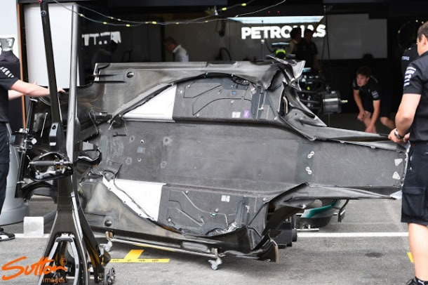
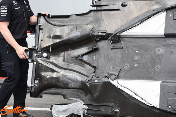
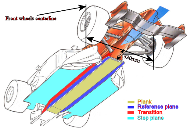
The undertray or underbody (pictured above: Nico Rosberg’s 2012 Mercedes AMG F1 W03; click for a larger image) is aerodynamically the strongest contributor to lap time. A very low drag-to-downforce ratio is an important design consideration. The underbody works in very close relationship with the front wing and splitter at the front of the car (feeding air to the underbody) and the diffuser at the rear (extracting air from beneath the car). A Formula 1 car produces much of its downforce from its underside, and each component can be thought of as a link in a long chain. Changing one without altering the rest throws everything out of alignment, and the car’s aerodynamics simply will not work as intended.
Regulations
F1 rules prohibit under-car shaping or venturis and mandate a minimum ride height enforced by a relatively low-tech wear plank attached underneath the car. The underbody must, by the rules, be completely flat, except for the plank and reference plane. However, there is still scope to shape the diffuser area directly under and behind the rear axle line.
As part of the package of aerodynamic changes designed to reduce downforce for 2009 and again for 2011, the diffuser underwent complex modifications. Moves to create a more standardised shape removed the height difference between the central and two outer sections, and all three channels became taller – 175 mm rather than 125 mm. The diffuser was also moved rearward, with its trailing edge now 350 mm behind the rear axle, whereas previously it was level with the rear axle.
The diffuser alone can produce significant downforce, approximately 35% of the total car downforce.
Aerodynamic Tricks
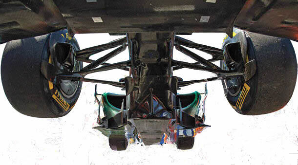
Teams employ various techniques to increase underbody and diffuser efficiency. For example, the forward barge board visible on the Mercedes F1 car pictured above acts solely as a vortex generator. These are cambered like a wing. The rotational direction of the vortex is counterclockwise, and because the vortex is travelling downward, it sends downwash approaching the underbody, feeding it with additional air and acting as a curtain – a highly favourable arrangement that essentially generates more downforce. The car’s keel splits the column of incoming air underneath the monocoque sideways and out of the way. It is carefully shaped and designed with the bargeboards in mind to generate higher airspeed and consequently lower pressure.
The sculpted sidepod turning vanes play a vital role in routing the dirty, turbulent wake of air coming off the front tires. They delay the point at which the front-wheel dirty wake begins entering under the floor and reducing downforce.
The leading edge of the floor generates vortices that spin down underneath the floor along the edge of the reference plane. All of this vortical action reduces the total pressure under the floor and provides additional downforce.
The Stepped Floor
The complication for perfect diffuser and floor performance arises from the shape of the Formula 1 car’s underbody. The area under the car is regulated to form essentially two flat surfaces. The stepped underbody was introduced to reduce the effectiveness of the diffuser, and the plank was introduced to prevent teams from running very low ground clearances that would enhance the diffuser effect.
All relative data regarding the underbody is precisely described in the FIA rules, though these regulations are exceedingly complex. In the FIA Technical Regulations, underbody or undertray surfaces are called “Bodywork facing the ground,” and the terms “diffuser” or “wing” do not appear. As with any bodywork in the rules, these parts are not allowed to move or flex more than specified. For the floor, there are few deflection tests commonly carried out during crash testing, the main ones being the splitter deflection test and fuel tank penetration test carried out from below the floor.
Underbody Components
Plank
There is an article in my F1 dictionary dedicated to the plank or skid block as it is called in F1 circles, so you can check there, but I will describe it here again in a shorter version.
Beneath the reference plane lies the skid block or “plank,” running from the frontmost point of the reference plane at 330 mm behind the front wheel centreline to the rear wheel centreline. It is not considered part of the floor for measurement purposes and exists only to enforce a minimum ride height.
It must be made from a material with a specific gravity between 1.3 and 1.45, to prevent excessively heavy or hard planks from producing a performance benefit or lowering the car’s centre of gravity. Typically, the plank is wood-based – either jabroc (a laminate of beechwood) or more exotic blends of woods and resins similar to MDF.
It must measure 300 mm in width with a tolerance of 2 mm. Although it decreases in thickness toward the edges to allow a smooth design, the plank most importantly, when measured through six pre-cut 50 mm diameter holes, has a tolerance of just 1 mm on its 10 mm thickness. Holes in the plank allow thickness measurement and enable the car’s reference plane to sit directly on the FIA scrutineering platform for legality checks over the course of a GP weekend.
Reference Plane
After ground effect was banned and the flat-bottom rule introduced in 1983, the speed of the car and downforce produced by the flat floor increased year after year. The flat-bottom rule was revised again after Ayrton Senna’s death in 1994, and from that year the floor has had to incorporate a step along its length. This produces the stepped shape visible in the car’s frontal profile, with the reference plane sitting lowest in the middle.
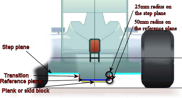
The reference plane, from which all heights are measured (the datum for all other measurements), is defined as the lowest part of the floor (excluding the plank). It runs along the centre of the car and must meet minimum width and length requirements. It starts on the splitter (T-Tray or Bib) 330 mm behind the front wheel centreline, extends to the rear wheel centreline, and must be between 300 mm and 500 mm wide and symmetrical about the car centreline. The reference plane must have a 50 mm radius (+/- 2 mm) on each front corner when viewed from directly beneath the car. At its sides, it transitions through radiused edges and a transition plane (or step) to the step plane.
Step or Transition
Between the reference plane and step plane is the step or transition. The rules mandate a vertical surface of 50 mm between the reference plane and step plane. Any intersections of these surfaces may have a radius no greater than 25 mm on the step plane and no greater than 50 mm on the reference plane. All parts lying on the reference and step planes, plus the transition between them, must produce a uniform, continuous, and rigid surface with absolutely no freedom of movement relative to the body of the car.
Step Plane
The larger, higher area of floor is the step plane, which must be 50 mm above the reference plane. It starts 330 mm behind the front wheel centreline and extends to the rear wheel centreline. It is an extremely important area because even though its curvature is banned, the flat bottom creates over a third of the car’s downforce – the car’s aerodynamics work best the closer they are to the ground, making this an area the FIA is keen to restrict.
The step plane defines the level at which any bodywork viewed from the car’s underside (and not on the reference plane) must stop. When looking up from below, all bodywork (bargeboards, sidepods, winglets, grilles) must be hidden. No unsprung part of the car may be visible from below the floor – except suspension, wings, and rear-view mirrors. This also means no holes can be made in the floor to allow air to flow in or out.
Dimensional tolerances are permitted: a vertical tolerance of +/- 5 mm across the reference and step planes, and a horizontal tolerance of 5 mm when assessing whether a surface is visible from beneath. All surfaces must be flat and produce a uniform, continuous, rigid surface. A large clearance is mandated around the rear wheel to prevent teams from sealing the floor against the rear tires.
Diffuser
To know more about the diffuser or exhaust blown diffuser, check my articles with more detailed explanation.
A purely flat floor would probably produce lift rather than downforce, so the rules have allowed a diffuser at the rear of the underbody since 1983. Before that date, there were no rules demanding floor dimensions, and diffusers were the full-length ground-effect tunnels that typified the wing cars of the late 1970s and early 1980s.
A diffuser creates downforce by establishing a pressure differential and serves to eject air from the car’s underside. This pulling action decreases the velocity of air below the car, so the more slowly moving air above pushes the car toward the ground – low pressure beneath and higher pressure above. The larger a diffuser, the greater its expansion ratio and therefore its potential to create downforce. From 2009, diffusers were limited to a simple 1000 mm width, 350 mm length, and 175 mm height. For 2011, the height was further reduced to just 125 mm, massively reducing the diffuser’s downforce potential compared with previous rules. Diffusers may have fences, but the fences and diffuser itself must not form undercuts when viewed from below.
Exploitation of the Rules
Over the years, teams have exploited these rules in various ways.
Teams converge the sides of the step plane toward the rear of the car into a point. The edges of the step join into a V-shape just before the rear axle line. This convergence accelerates the airflow along the vertical edge of the step, which is otherwise of poor quality. Teams use the shape of the step plane’s trailing edge to improve the flow and pull air through the diffuser. The resulting V-shape at the start of the centre channel is also useful for accommodating the end of the gearbox.
Another development is the addition of a ramp low in the centre channel, starting at the axle line and positioned as low as possible, to pull air from the space between the track and the plank.
During the double-diffuser period of 2009 and 2010, teams exploited the wording of the “floor continuous surface” rule by opening holes in the vertical transition surface. Since the rules stipulated that no bodywork should be visible when viewed from below, and any part of the floor must be a “continuous surface,” holes in the vertical plane satisfied both requirements. The step effectively formed two separate but individually continuous surfaces, allowing airflow to pass up above the step plane into the upper deck of the diffuser. This rule was clarified for 2011, now requiring a “single continuous surface” under the floor.
Additionally, the flexibility of the splitter was brought into question. Teams were believed to be flexing the splitter upward, and more stringent tests were introduced in 2010 to address this.
Mercedes AMG F1 Undertray