Transmission
Overview
Just like a family road car, F1 cars have a clutch, gearbox, and differential to transfer approximately 800 bhp to the rear wheels. Although they serve the same function as on a road car, the transmission system in an F1 car is radically different.
A good engine must be installed well to perform to its ultimate ability, and it must output its power to the wheels in the best way possible. The engine is connected to the flywheel, which is linked to the drive shaft via the clutch plates. The drive shaft goes into the gearbox, which is connected to the axles (and therefore the wheels) through the gears and differential.
The Clutch
Having explained how the gearbox works in the gearbox article, the next thing to consider is how to change between gears. This is done using the clutch. With the gear wheel on the end of the drive shaft rotating in the gearbox, it is not easy to move it through the gears to mesh with another gear. Any attempt to do so without disengaging the clutch will result in the grinding noise heard from a poorly driven car – that is the rotating gear wheel grinding against one of the gears in the gearbox.
This is why the drivetrain incorporates a clutch. In F1, multi-plate clutch designs give enhanced engine pick-up, and the lightweight designs with a small diameter mean low inertia, allowing faster gear changes. The flywheel on an F1 car is just 10 centimetres in diameter. The drivers do not normally use the clutch manually, apart from moving off from standstill, during pit stops, and in case of emergency or spin. They simply press a gear change selector lever behind the wheel to move to the next ratio. The on-board computer automatically cuts the engine, depresses the clutch, and switches ratios in the blink of an eye.
Semi-Automatic Operation
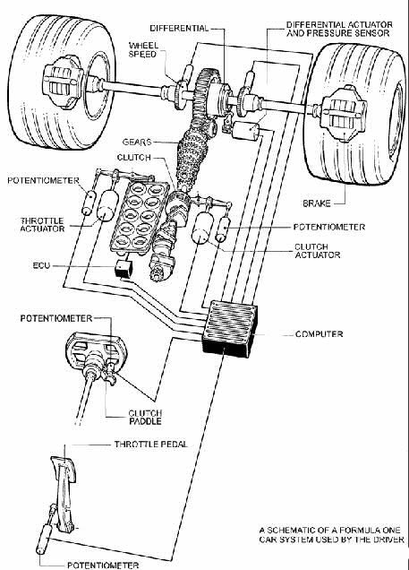
In the world of the F1 semi-automatic gearbox, there is no need for the driver to think about clutch operation – everything is electronically controlled. All the driver is required to do is pull a paddle when wanting to change up or down a gear, and the electronics controlling the gearbox and clutch do the rest. The advantages, beyond allowing the driver to keep both hands on the wheel at all times, are that the whole process takes a split second (much quicker than a manual clutch could be operated) and that clutch pad wear is reduced because the clutch is never held half-on, increasing reliability.
The engine and transmission of a modern Formula One car are some of the most highly stressed pieces of machinery on the planet.
Durability Requirements
Traditionally, the development of racing engines, transmissions, and other F1 components has followed the rule of the great engineer Ferdinand Porsche, who stated that the perfect race car crosses the finish line in first place and then falls to pieces. Although this is no longer strictly true – regulations now require engines to last five race weekends and gearboxes four – designing modern Formula One engines remains a balancing act between extractable power and the need for just enough durability.
The Race Start
The start phase in Formula 1 is extremely important – the beginning and first highlight of every race. So much is at stake during the first few hundred metres that some of the most sophisticated and secret engineering on the cars is devoted to helping the driver during those first couple of seconds. The prize is the order of cars into the first corner, which in modern racing so often dictates the order for the rest of the race.
Previously, drivers could rely on highly sensitive and fast electronics during this critical phase. From 2008 onwards, the regulations forbid the use of any start electronic assistance and traction control in the race phase. With a common ECU, this is easily controlled by the FIA. Sensitive manual control during the start is once again required – and that should be taken literally, because in F1 the commands to the gearbox and clutch are distributed by means of steering-wheel-mounted paddles. Transmissions may not feature traction control systems, or devices that help the driver to hold the clutch at a specific point to aid getaway at the race start.
ZF Sachs Clutch Technology
After abolishing all electronic help during the start phase, Thomas Rudolf, engineer for clutch systems at ZF Sachs Race Engineering, explained that the return to manual control was viewed with mixed feelings from a technical perspective.
The ZF Sachs AG motorsport department equips the Formula 1 teams of Ferrari, Honda, Toyota, and others with clutches and shock absorbers.
With electronic control and help, the clutch managed surplus power through slippage between carbon clutch plates. As a result, this critical interface in the drivetrain was subject to extremely high loads – up to two seconds and in exceptional cases up to ten seconds – with temperatures in excess of 1,000 degrees Celsius.
Rudolf explained the challenge: in contrast to a normal car with a clutch pedal, the Formula 1 driver does not feel a pressure point with the paddle. The driver must remember at which paddle position the gear engages. It is a balancing act. Even top drivers can slip the clutch for only a maximum of half a second to help pull away. This is not enough and is only a quarter of the time that the electronic launch function required.
A few key figures illustrate the extreme loads on the F1 clutch from ZF Sachs, weighing no more than roughly 860 grams: the diaphragm springs apply 1.6 tonnes of pressure to the three clutch plates, and the tiny 100-millimetre titanium housing withstands temperatures of up to 700 degrees Celsius.
The new regulations do not guarantee an easier time for the clutch, however. Where the human element is involved, mistakes happen. If a driver misses the engagement point and releases too fast, the engine could stall; the driver disengages the clutch again, lets the engine revs skyrocket, and tries to reengage. Often, the process is repeated several times. As a result, even higher loads and temperatures can occur. Even if such mistakes are not the rule, engineers who construct the clutch must make provision for them. That is why they refrained from reducing the reserves that were freed by the abolition of electronics.
In fact, the Sachs Formula 1 clutch of 2008, at the same overall dimensions as its predecessor, was even more efficient. The technicians reduced the clutch hub size of the previous model, gaining more room for the stressed carbon disc friction faces. The diaphragm springs, which clamp the friction plates with a force of 1.6 tonnes, are produced from a special steel alloy resistant to temperatures of up to 700 degrees Celsius. The tiny titanium housing with a diameter of around 100 millimetres, thanks to a further optimised machined contour, is more robust. Sachs expected component longevity to have increased by a factor of three. The housing is particularly stressed by engine vibrations – although the engines must last two race weekends, the lighter they are, the more they vibrate, which wears out the clutch housing.
The new gearboxes that must last for four races have no influence on the clutch. From a technical point of view, Formula 1 cars do not require a clutch to shift in the higher gears. The loads resulting from this have already been accounted for over the years.
External Clutch Disconnect
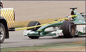
For safety reasons, all cars must have a means of disengaging the clutch that is operable from outside the cockpit by marshals. This control is usually situated just ahead of the cockpit opening and is marked on the car’s body by a red letter “N” within a white circle.
![]()
Driveshaft
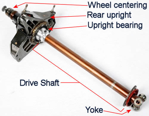
When the throttle is pressed, the engine spins the flywheel. The flywheel transfers energy to the gearbox, which is connected through the gears and differential to the axles and therefore the wheels. One very important part of the machinery lies between the differential and the wheel: the driveshaft, sometimes called a half shaft. It is the only link between the gearbox/differential and the rear wheel.
While horsepower cannot be gained through the driveshaft, it can certainly be lost. Driveshafts are carriers of torque: they are subject to torsion and shear stress, equivalent to the difference between the input torque and the load. They must therefore be strong enough to bear the stress whilst avoiding too much additional weight, as that would increase their inertia.
To allow for variations in alignment and distance between the differential and upright, driveshafts must incorporate one or more universal joints. In Formula 1, there is typically one joint called a yoke, slip yoke, or slip joint, located at the connection point between the differential and the driveshaft. The slip-yoke and the pinion-yoke take considerable abuse in a high-performance application. These are the physical connectors to the transmission, driveshaft, and differential. All torque and power is transferred through these joints.
Driveshaft Materials
The material of the driveshaft is as important as its length and diameter. Historically, driveshafts were made of chrome-moly or lightweight aluminium. Chrome-moly is one of the strongest metallic materials, commonly seen in Pro Stock cars. Chrome-moly steel tubing can be heat-treated, raising torsional strength by 22% and increasing critical speed by 19%. The problem with steel is its weight, which increases the load on the drivetrain.
Aluminium is probably the most common performance driveshaft material. A lightweight aluminium shaft reduces rotational mass, freeing up horsepower and reducing parasitic loss. An aluminium driveshaft can support 900 to 1,000 hp, making it a great lightweight choice for most applications. However, it is not as strong as steel.
Modern Formula 1 cars use carbon fibre. Carbon-fibre tubes are the most expensive but also the most efficient. For power figures up to 1,500 hp, carbon fibre is an excellent choice. Carbon-fibre driveshafts are not only strong but also have a surprisingly high torsional strength, resisting twisting and reducing the shock factor on the rear end. Carbon fibre also has the highest critical-speed modulus of elasticity, meaning the shaft will not flex at lower speeds unlike other materials. Coupled with the highest critical speed and the lightest weight, a carbon-fibre driveshaft can free up some horsepower over aluminium, and especially over chrome-moly tubing. When winning is everything, that can make the difference.
Critical Speed
The most common cause of driveshaft failure is reaching critical speed. All driveshafts have a critical speed – the RPM at which the driveshaft becomes unstable and begins to bend into an S-shape. The longer and smaller in diameter a driveshaft is, the lower its critical speed. Critical speed is felt as excessive vibration that will cause the unit to fail. To calculate the critical speed, the length, diameter, wall thickness, and material modulus of elasticity must be known. The modulus of elasticity of the shaft material is an important part of the equation. For steel, the basic MOE is 30; for aluminium it is 10; and for carbon fibre it depends on the manufacturing processes used.