Shock Absorbers
Brief History
In the early 1900s, cars still rode on carriage springs. After all, early drivers had bigger things to worry about than the quality of their ride – like keeping their cars rolling over the rocks and ruts that often passed for roads.
Pioneering vehicle manufacturers were faced early on with the challenges of enhancing driver control and passenger comfort. Early suspension designs found the front wheels attached to the axle using steering spindles and kingpins. This allowed the wheels to pivot while the axle remained stationary. Additionally, the up-and-down oscillation of the leaf spring was damped by a device called a shock absorber.
|
Early shock absorbers |
These first shock absorbers were simply two arms connected by a bolt with a friction disk between them. Resistance was adjusted by tightening or loosening the bolt.
As might be expected, these early shocks were not very durable, and their performance left much to be desired. Over the years, shock absorbers have evolved into far more sophisticated designs.
How Shock Absorbers Work
Despite what many people think, conventional shock absorbers do not support vehicle weight. Instead, the primary purpose of the shock absorber is to control spring and suspension movement. This is accomplished by turning the kinetic energy of suspension movement into thermal energy (heat), which is dissipated through the hydraulic fluid.
Technically, shock absorbers are called dampers. More precisely, they are velocity-sensitive hydraulic damping devices – the faster they move, the more resistance there is to that movement. They work in conjunction with the springs. The springs support the car’s weight and allow movement of the wheel, transforming the energy in road shocks into kinetic energy of the unsprung mass, whereupon it is dissipated by the damper as heat. The damper achieves this by forcing gas or oil through a constriction valve (a small hole). Adjustable shock absorbers allow the size of this constriction to be changed, thus controlling the rate of damping. The smaller the constriction, the stiffer the suspension.
Shock absorbers are basically oil pumps. A piston is attached to the end of the piston rod and works against hydraulic fluid or gas in the pressure tube. As the suspension travels up and down, the hydraulic fluid is forced through tiny holes, called orifices, inside the piston. However, these orifices let only a small amount of fluid through the piston. This slows down the piston, which in turn slows down spring and suspension movement.
The amount of resistance a shock absorber develops depends on the speed of the suspension and the number and size of the orifices in the piston. Because of this feature, shock absorbers adjust automatically to road conditions.
As a result, shock absorbers reduce the rate of:
Shock absorbers work on the principle of fluid displacement on both the compression and extension cycles. A typical car or light truck will have more resistance during its extension cycle than its compression cycle. The compression cycle controls the motion of a vehicle’s unsprung weight, while the extension cycle controls the heavier sprung weight.
Compression Cycle (Bump)
Compression cycle or Bump
During bump, the dampers and springs absorb upward movement from cornering or road irregularities (the springs store some of this energy). Acceleration, braking, or cornering in this state will also vary due to the various load rates, so it is important to have enough bump stiffness to deal with uneven surfaces.
If there is too much damping, it is effectively like running no suspension, and any upward motion will be transmitted directly to the chassis. Over-damping results in an increase in the loads acting on the suspension and the tires. The handling will feel very harsh and hard, which will affect street driving in terms of comfort and may not be desired for a daily driver.
Both under-damping and over-damping are undesirable, as they reduce the handling of the car and affect acceleration, braking, and cornering loads.
At the piston, oil flows through the oil ports, and at slow piston speeds, the first-stage bleeds come into play and restrict the amount of oil flow. This allows a controlled flow of fluid from chamber B to chamber A.
At high speeds, the limit of the second-stage discs phases into the third-stage orifice restrictions. Compression control is the force that results from a higher pressure present in chamber B, which acts on the bottom of the piston and the piston rod area.
Extension Cycle (Rebound)
Extension cycle or Rebound
During rebound (following the bump compression phase), the dampers extend back to their original positions, using up the stored energy from the springs. The rebound stiffness needs to be set at a higher value than the bump setting, as the stored energy is being released. If there is insufficient damping on the rebound, the wheel will quickly return through the static level and start to bump again, with the bouncing effect unsettling the suspension with little control.
If there is too much rebound stiffness, the wheel could remain held in the wheel arch longer than needed, effectively losing contact with the road as the force pushing the wheel back down is slower to respond to the changing surface level. This state is also far from ideal, and it is important to ensure a good level is set for optimal tire contact with the road.
As the piston and rod move upward toward the top of the pressure tube, the volume of chamber A is reduced and thus at a higher pressure than chamber B. Because of this higher pressure, fluid flows down through the piston’s 3-stage extension valve into chamber B.
However, the piston rod volume has been withdrawn from chamber B, greatly increasing its volume. Thus the volume of fluid from chamber A is insufficient to fill chamber B. The pressure in the reserve tube is now greater than that in chamber B, forcing the compression intake valve to unseat. Fluid then flows from the reserve tube into chamber B, keeping the pressure tube full.
Extension control is the force present as a result of the higher pressure in chamber A, acting on the topside of the piston area.
The Piston
The piston is attached to the end of the piston rod and works against hydraulic fluid in the pressure tube. As the suspension travels up and down, the hydraulic fluid is forced through tiny holes, called orifices, inside the piston. The picture shows a modern design for use in road car dampers.
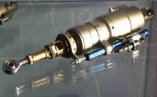
Adjustable Dampers
The image above shows a typical modern coil-over-oil unit that has been in use for a long time with sports cars and motorcycles. This is an all-in-one system carrying both the spring and the shock absorber. The adjustable spring plate can be used to make the springs stiffer or looser, while the adjustable damping valve controls the rebound damping of the shock absorber. More sophisticated units have adjustable compression damping as well as a remote reservoir. While this level of engineering is not typical on car suspension, most motorbikes do have preload, rebound, and spring tension adjustment, and these adjustments are standard in racing.
Shock absorbers work in conjunction with springs and stabilisers. Dampers provide a resistance for the spring to work against. The purpose of this is to prevent the spring from oscillating too much after hitting a bump. Ideally, the spring would contract over a bump, then expand back to its usual length straight afterwards. This requires a damper to be present, as without one, the spring would contract and expand continually after the bump, providing a rather horrible ride.
Racing Damper Setup
Modern F1 and racing shock absorbers can be regulated for bump and rebound, but only before the race. The shock absorber does not absorb impacts; rather, it damps the motion of the car and the oscillations of the spring after travelling over bumps and dips. When weight transfers from back to front and side to side (roll), or when the car goes over a bump, the wheels/tires compress (bump), and when past the bump, the wheel returns to equilibrium after the compression (rebound). This is basically the suspension movement.
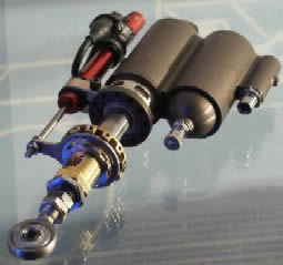
Williams dampers with movement sensor attached (red and blue things). Right hand damper is with separated gas tank
Bump and Rebound Settings
Bump is the rate at which the shock compresses.
Rebound is the rate at which the shock decompresses.
Bump damping affects how far and fast the suspension travels up. When the suspension is on its way back down, rebound damping affects how far and fast it goes the other way. More precisely, bump damping affects the compression rate, while rebound damping affects the expansion rate.
If bump damping is made too stiff, the car will be skittish over rough surfaces. Rebound damping also affects steering as the car transitions into and out of corners.
In general, stiffer absorbers are better suited for flat tracks with sharp turns. They prevent the springs from compressing too quickly, which decreases the dip experienced when cornering and braking. Softer adjusted absorbers are better suited for winding, coiling tracks, but they will also lengthen braking distance.
So having bump at (for example) a value of 9 and rebound at a value of 2 makes the car stiffer when absorbing a bump – compression is harder. The suspension on rebound will not return as fast. This suppresses weight transfer. However, the tire will not make contact with the ground fast enough, causing slip that can induce oversteer.
On the other hand, bump at 2 and rebound at 9 absorbs more bumps but returns the shocks the opposite way too fast. The car may literally jump over small bumps. This is also undesirable, as the tire is not in contact with the road. Bump at 7 and rebound at 6 keeps the tires stiff and returns them to the ground slowly. Bump at 6 and rebound at 7 results in good stiff compression of the shocks, and the slightly higher rebound means the tires return a bit faster to the ground but not too fast. This is the ideal configuration: a slightly higher rebound value.
ZF Sachs Rotational Dampers
When Ferrari presented the F2003-GA at the beginning of 2003, attentive listeners noted a completely new rear suspension development.
The specifics of what was new about Ferrari’s rear suspension were kept under close cover, and for good reason: trying to spy out a competitor’s concept, understand it, and copy it is common practice in Formula 1. Copying the cars driven by Michael Schumacher and Rubens Barrichello was well worth the effort: the Scuderia Ferrari became even more dominant after fitting their cars with the new rear suspension. No fewer than 17 victories were clinched by Ferrari’s German-Brazilian driver pairing since the new suspension component was first used at the Spanish Grand Prix in May 2003, including six one-two victories in the 2003 season.
Despite all the secrecy, after more than a year, clever rivals discovered what was behind the revolutionary new design: a development by ZF Sachs Race Engineering GmbH.
Conventional dampers are installed on the car by securing one end to the gearbox case and the other end to a rocker that re-orientates the movement from the pushrod into the movement of the damper. The rocker can be made up of several levers splined to a single shaft and requires several bearings to make the suspension movement friction-free. This amounts to quite a lot of separate components, all of which need space to fit.
How Rotational Dampers Work
The damper concept was revolutionised in a joint project with Scuderia Ferrari engineers. Instead of the three conventional dampers of the rear suspension, two rotational dampers integrated in the rocker now handle the bulk of the work, replacing two of the conventional dampers. The pivoted rocker is a type of “triangular lever arm” that diverts jounce and rebound motion from the wheel to the spring, anti-roll bar, and – in previous systems – to the conventional dampers.
The new rockers with integrated rotational dampers are high-tech components made by Sachs. The Formula 1 cars from Maranello used only one conventional damper in the middle, which responds when the entire chassis – due to downforce at high speeds, for example – is pushed against the track. Approximately nine months of development time were invested in the rotational damper.
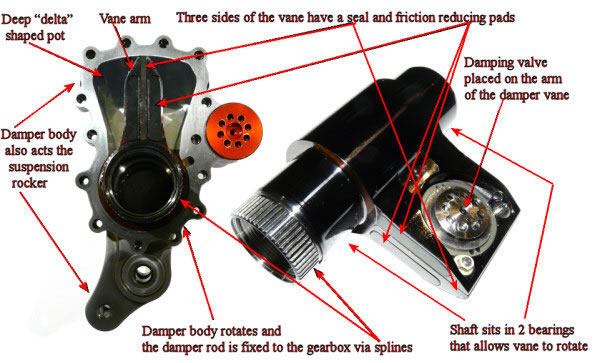
Essentially, the rotary damper converts the axial movement of a linear damper into a rotational movement. All the components have the same function; they just move in a different direction. The damper body is a deep “delta”-shaped pot, and the damper rod, known as the vane, rotates in the body. The vane arm sweeps through a small angular rotation in the delta-shaped pot section of the damper body. The damping valves are placed in the face of the damper vane and work in exactly the same manner as a linear damper.
In brief, the system operates as follows: the motion of the rear suspension link during jounce and rebound is transmitted to the rotary damper body acting as the rocker. The damper body rotates while the damper rod with its vane is fixed to the gearbox via splines. As the damper body rotates and the vane remains static, the vane moves through the oil-filled cavity and “pumps” oil from one side to the other through valves with specifically defined oil ports to generate the necessary damping forces. The rotational damper consists of five main components contained in a housing machined from a billet of titanium meeting aviation industry specifications. The major know-how, however, is found in the particular sealing technology used, which ZF Sachs had previously tested in active anti-roll bar systems for production cars. When operating in the Formula 1 Ferrari, the damper is subjected to approximately 160 bar of internal pressure.
As the housing also acts as the suspension rocker, there are elements machined into its outer face to provide this function. The housing acts as the rocker linkage, so a rocker arm is part of the machined shape. This accepts the anti-roll bar and all other linkages.
The damper vane is machined from a single solid block of titanium. It is made of two shapes: a shaft that sits in bearings allowing the arm to rotate, and a flat plate formed into the vane. This part is the equivalent of the linear damper’s damping rod. This arm needs to be closely fitted to the damper cavity to accurately control oil for an effective damping effect. Three sides of the vane have a seal and friction-reducing pads. The edges need to be sealed against the housing. A single square-edged seal is fitted into a machined groove around the periphery of the vane. The damper valve is a simple circular shim stack arrangement fitted to a hole machined into the vane’s face. This valve setup is almost identical to the setup used on the end of a linear damper. This is perhaps the only aspect of the rotary damper that directly mirrors a linear setup.
Advantages and Disadvantages
Rotational dampers offer a host of benefits. First and foremost, they save space, as the conventional dampers are omitted. Because of the rocker integration, the system is very stiff and direct, with little loss due to backlash in linkages, ball joints, and similar components, which means it has good high-frequency response. This allows a more compact gearbox design and thus further improvements in aerodynamic efficiency. Besides space, rotational dampers save approximately 50 to 70 grams of weight – a significant reduction in the high-tech world of Formula 1 racing. There is also considerably less thermal stress on the new rotational dampers than on the previously used conventional units integrated in the extremely hot gearbox. Like the conventional system, the new solution operates with non-adjustable dampers during Grand Prix weekends. Engineers calibrate the dampers prior to the competition based on the results of dynamometer and track testing.
As for negatives, there is a much more complicated sealing arrangement in the damper. The high internal pressure requires the hydraulic seals to have reasonable preload, which induces a large amount of friction and hysteresis. This internal pressure also leads to structural issues: the high internal pressures can cause local deformation of the housing as well as deformation of the vane, leading to increased friction and fairly inconsistent damping characteristics. Initial development started with aluminium, then titanium and steel options were explored to gain stiffness and reduce the issues caused by deformation.
Beyond the technical arguments, there is the matter of cost. Rotational dampers are complex, high-precision parts and are very expensive, so they do not represent good value for money relative to the weight saving. Depending on the specification, the price is in the region of about $20,000 per piece. With these being sealed dampers for each setup, a pair of dampers costing $40,000 would be on the car, with a multitude of other damper pairs in the pits, each set up for different damping characteristics.
Legacy
The engineering principle of the rotational damper successfully passed its “baptism of fire” in motor racing, followed by the consistent delivery of superior performance on the world’s circuits. However, the chances that normal road users will enjoy the benefits of this high-tech component are slim, as its price tag is ten times that of a conventional telescopic damper.