Pneumatic Valve Actuation
Valve Operation Basics
The characteristic and universally used mushroom or “poppet” valves (found in every four-stroke engine) open during their down-stroke and close during their up-stroke, until they make contact with their seats in the cylinder head.
Normally, the valve is operated by a “cam” system that controls valve opening (down-stroke), while valve “return” – the closing movement (up-stroke) – is the result of a spring’s action.
Valve Float and Valve Bounce
Valve float is an adverse condition that occurs when the poppet valves on an internal combustion engine valvetrain do not remain in contact with the camshaft lobe during the valve closure phase of the cam lobe profile. This reduces engine efficiency and performance and potentially increases engine emissions.
Valve bounce is a related condition where the valve does not stay seated, due to the combined effects of the valve’s inertia and resonance effects of metallic valve springs that effectively reduce the closing force, allowing the valve to re-open partially.
Renault’s Innovation
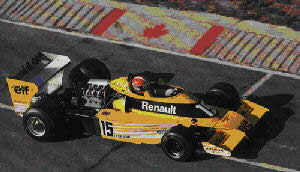
Renault has been a long-time influence in Formula 1. The first event considered to be a “Grand Prix” race, held at Le Mans in 1906, was won by a Renault.
In the modern era, Renault’s presence has been considerable. They ushered in the turbo era of the 1980s, taking advantage of a clause that allowed smaller, turbocharged engines. The rest of the manufacturers initially thought Renault was mistaken, but within a couple of seasons every engine on the grid was turbocharged. Eventually, the turbos had to be banned because the engines were simply too powerful, producing over 1,200 horsepower during the race and Porsche engines reaching 1,500 hp during qualifying.
Racing engines often failed at high RPM because mechanical springs were unable to close valves fast enough, leading to engine failure when pistons struck incompletely closed valves. For this reason, as many as three concentric valve springs, press-fitted into each other, were often used – not for more force (the inner ones had no significant spring constant), but to act as snubbers to reduce oscillations in the outer spring.
Overcoming the RPM Barrier
Stiffer valve springs can help prevent valve float and valve bounce, but only at the expense of increased friction losses. In Formula 1, various techniques have been used to offset the effect of stiffer springs, such as dual-spring and progressive-sprung valves, roller-tipped tappets, and ultimately pneumatic valves.
If a normal valve-spring engine had an upper RPM limit of about 10,000 rpm, that same engine design equipped with a desmodromic valve actuation system would be capable of 15,000 rpm and much more power. With a pneumatic system, there is practically no limit (in practice around 25,000 RPM). Previously used wire valve springs required huge amounts of development in their shape and material to reach rev limits of around 12,000-13,000 RPM. The pressure to deliver power from 3.5- and later 3.0-litre engines required ever higher rev ceilings, and metal springs could no longer be developed at the same rate as the rest of the engine.
How Pneumatic Valve Springs Work
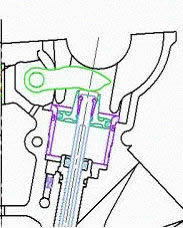
Pneumatic valve springs are metal bellows filled with compressed air, occupying roughly the same space as the metal springs they replace to close valves in high-speed internal combustion engines. This system was introduced in the mid-1980s in the Renault turbocharged RVS-9 1.5-litre Formula 1 engines. Renault’s innovation was to replace steel springs with lightweight compressed-air bellows that could respond more quickly and reduce the possibility of valve crashes (other than from leaking bellows).
Standard spring and Renault pneumatic valve actuation in open view. In the picture above, the spring is missing.
Renault’s Racing Success
Pneumatic valve springs gave Renault an advantage with its turbocharged engines, often said to be the most powerful. However, reliability issues and poor chassis handling kept the cars from success until 1989, when Renault provided Williams with its V10 engine to begin a winning streak. Renault returned to Formula 1 in the 1990s as an engine supplier, again using the pneumatic valve closure system. This was quickly adopted by every engine manufacturer in Formula 1. Renault won the constructors’ championship with Williams in 1992, 1993, 1994, 1996, and 1997, and with Benetton in 1995. Nigel Mansell, Alain Prost, Michael Schumacher, Damon Hill, and Jacques Villeneuve each won a drivers’ championship in the 1990s with Renault engines.
Technical Details
The technology of all current pneumatic valve return systems involves simply replacing the valve spring with a pneumatic spring, using an inert gas (nitrogen, which behaves substantially the same as air but is an inert gas that does not support combustion as air or oxygen does) as the compressive fluid. The camshaft exercises its normal precise control of the motion of each valve, and each pneumatic spring maintains the contact force between an individual valve assembly, cam, and tappet bucket during operation. Pneumatic valve spring systems are thus an improved replacement for mechanical springs. They are not a complete valve control system like a desmodromic operation, which uses no springs at all.
Pneumatic valve springs operate on a ring-main system with the essential back-up of a compressed gas cylinder, pressure regulators, one-way valves, and an oil scavenging system. The principal reduction in valve assembly mass is in the upper one-third of each valve spring. Although a net small reduction in valve assembly mass is possible, this is accompanied by added friction from the stem seal ring.
The pneumatic spring is not subject to fatigue failure or diminished damping with running time, unlike a mechanical spring. Valve lift is not constrained by spring wire maximum stress and stress-range limits. Renault reports that the rising-rate characteristics of the pneumatic spring assist in matching spring force to valve assembly inertia force requirements, particularly in their V10. The fundamental pneumatic spring advantage for very high-speed engines is that the natural frequency of the compressed gas column is in the order of eight times that of a steel wire coil spring.
The Inventor
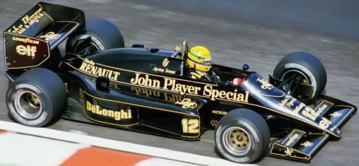
It was Jean-Pierre Boudy, the Chief Engineer of Engine Development at Renault Sport during the turbocharged V6 race engine era, who invented the first pneumatic valve spring system used in a competitive race car engine. The pneumatic spring-equipped Renault engine was first raced in a Lotus chassis driven by Johnny Dumfries and Ayrton Senna in 1986, at the beginning of the GP season.
Honda’s Implementation
The Honda RA122E/B (1992 V12 F1) ran with nitrogen pressure at 6-8 bar (87-116 psi) with the gas replenishment cylinder charged initially to approximately 150 bar (2,175 psi). Honda claimed a reduction of valve assembly reciprocating mass of 20% with similar levels of valve gear friction compared to conventional systems.
MotoGP Adoption
Pneumatic valve control became so compact and reliable that MotoGP also adopted it. All manufacturers use it except Ducati, which retains its desmodromic valve actuation. The pneumatic valve springs debuted in MotoGP in 2002 with the Aprilia RS3 Cube. In 2005, Team Roberts was the first to use pneumatic valves full-time in their KTM-powered bike. Today, almost all MotoGP teams use pneumatic valve technology on their bikes, including Yamaha, Suzuki, and Honda. The picture shows valve actuation with a pneumatic “spring” on the Yamaha YZR M1 MotoGP engine during the 2011 season.
Electro-Hydraulic Valve Research
While pneumatic valve springs have become standard in Formula 1 engines, Renault has been researching computer-controlled electro-hydraulic valves that use no camshaft, reducing moving parts while improving valve control. Pressure in the upper part of the valve piston (24) is controlled by an electro-actuated solenoid valve (EVA). In this way, it is possible to control the exact timing of valve opening. Oil for actuating valve movement is contained in a pressurised tank (32).
The lower part of the piston is under constant pressure to ensure fast closing of the valve. The pressure is contained in a separate pressurised tank (40).
Because this system has variable valve timing capabilities, it was never used in Formula 1. FIA technical rules consider variable valve timing to be illegal.
Regulatory Text
The FIA 2009 Formula One Technical Regulations state:
5.7 Variable geometry systems :
5.7.1 Variable geometry inlet systems are not permitted.
5.7.2 Variable geometry exhaust systems are not permitted.
5.7.3 Variable valve timing and variable valve lift systems are not permitted.
5.10 Engine actuators :
With the following exceptions hydraulic, pneumatic or electronic actuation is forbidden :
a) Electronic solenoids uniquely for the control of engine fluids ;
b) Components providing controlled pressure air for a pneumatic valve system ;
c) A single actuator to operate the throttle system of the engine ;
d) Any components required as part of a KERS.
5.15.6 Valves must be manufactured from alloys based on Iron, Nickel, Cobalt or Titanium.
Hollow structures cooled by sodium, lithium or similar are permitted.