NACA Duct
A Brief History

The National Advisory Committee for Aeronautics (NACA) was a United States federal agency founded on 3 March 1915 to undertake, promote, and institutionalise aeronautical research.

On 1 October 1958, the agency was dissolved and its assets and personnel were transferred to the newly created National Aeronautics and Space Administration (NASA).
The act of Congress creating NACA reads: “…It shall be the duty of the advisory committee for aeronautics to supervise and direct the scientific study of the problems of flight with a view to their practical solution….”
In 1922, NACA had 100 employees; by 1938, it had 426. In addition to formal assignments, staff were encouraged to pursue unauthorised “bootleg” research, provided it was not too exotic. The result was a long string of fundamental breakthroughs, including the “NACA engine cowl” (1930s), the “NACA airfoil” series (1940s), and the “area rule” for supersonic aircraft (1950s).
The name NACA remains familiar in the automotive world for the NACA duct, a type of air intake, and in the aircraft industry for the NACA airfoil and NACA cowling series, which are still used in new designs.
What Is a NACA Duct?
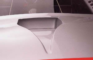
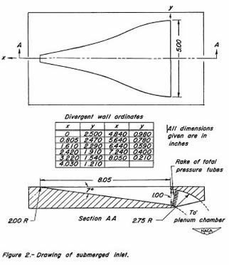
In racing, drag is a constant enemy. Every bit of drag on a car increases the amount of fuel needed and limits maximum speed, making drag minimisation critical. The NACA duct brings air into a vehicle with minimal drag increase. It is a common form of low-drag intake design, and when properly implemented, it allows fluid to be drawn into an internal duct – often for cooling purposes – with minimal disturbance to the external flow. The design was originally called a “submerged inlet,” consisting of a shallow ramp with curved walls recessed into the exposed surface of a streamlined body, such as an aircraft. It is especially favoured in racing car design.

How It Works
The purpose of a NACA duct is to increase the flow rate of air through it without disturbing the boundary layer. When the cross-sectional flow area of the duct is increased, static pressure decreases and the duct effectively acts as a vacuum cleaner – but without the drag of a protruding scoop. The reason the duct is narrow at the entrance and then suddenly widens in a graceful arc is to increase the cross-sectional area gradually, preventing airflow separation and turbulence (which would cause drag).
NACA ducts are useful when air needs to be drawn into an area not exposed to the direct airflow that a conventional scoop can access. They are commonly found along the sides of cars or on engine bonnets. The NACA duct takes advantage of the boundary layer, a layer of slow-moving air that “clings” to the bodywork, especially where the bodywork flattens or does not accelerate or decelerate the airflow. Areas like the roof and side body panels are good examples. The longer the surface, the thicker the boundary layer becomes (which itself is a growing source of drag).
This design works because the combination of the gentle ramp angle and the wall curvature profile creates counter-rotating vortices that deflect the boundary layer away from the intake and draw in the faster-moving air, while avoiding the form drag and flow separation that can occur with protruding inlet designs. This type of flush inlet generally cannot achieve the larger ram pressures, but it is common for engine and ventilation intakes.
Applications and Limitations
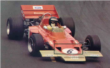
The original goal of the NACA duct was not applications requiring maximum pressure recovery (ram pressure), unlike the prominent ram-type intakes seen behind the driver’s head in Formula 1 cars. Instead, the application was intended to minimise the parasitic drag added to the aircraft or car. This works well for air vents, as drag remains low whether the vent is open or closed. NACA ducts are not particularly useful for engine air intakes but are well suited for cooling air supply. They are low-drag intake channels used mostly for a variety of cooling requirements such as brakes, engine, and driver cooling. The distinctive geometry includes a widening mouth at the inlet, with the duct floor slightly expanding the flow area.
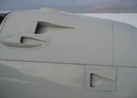
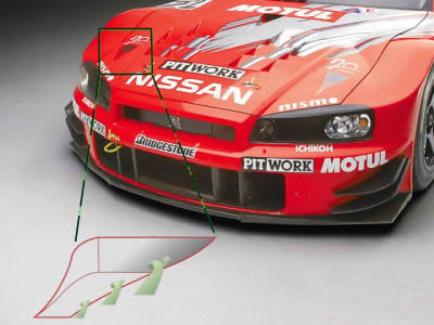
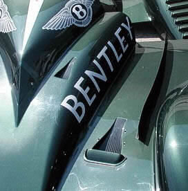
Sometimes, to increase air supply, constructors add a small scoop, as on the Bentley LMP car shown below. Extensive wind tunnel testing of various designs has resulted in the best compromise between flow rate and drag. In the case of this GT car, the NACA duct on the bonnet feeds small airboxes that direct cool air to the front brakes. Sharp wall edges effectively generate vortices that help keep the flow attached to the diffuser-like sloped floor. These edges must be sharp (unlike many aftermarket copies); otherwise the flow separates, reducing the duct’s efficiency.
|
|
Practical Implementation Tips
A few considerations when implementing a NACA duct on a race car:
-1: Design is critical. The duct must have the correct wall angles (sharp), base slope, and width-to-depth ratio relative to speed.
-2: The duct needs to be installed in an area of high pressure. A leading edge of a car is an ideal location.
-3: Quality matters. Edges on the slopes must be sharp; otherwise the flow separates, reducing efficiency.
-4: A NACA duct is only useful in applications where a modest amount of airflow is acceptable – less than a protruding scoop would provide.
-5: For meaningful airflow, the duct must be placed in a region with a positive pressure gradient – where the air sees the body as increasing in size, not remaining constant or decreasing.
-6: NACA ducts do not work well, or at all, when placed on negative-pressure areas.