Fuel Map or Fuel Table
Introduction
Modern automotive technology relies on electronically controlled devices to monitor and operate the car’s engine. One of the most important processes determining engine performance is fuel injection – the process that causes combustion in an engine by combining fuel and air.
In the past, internal combustion engines used carburettors to mix fuel and air. As cars became more complex and government regulations related to exhaust emissions became stricter, today’s engines use computer-controlled systems with electronic fuel injection. These systems can more precisely control the flow of fuel to the engine, allowing for precise mixing of fuel and air. This results in optimum engine performance, better fuel economy, and lower exhaust emissions – or more power and torque, depending on the objective. The efficiency and precision of the fuel injection system also determines how well the engine runs and ultimately how well the car performs.
Pedal Maps and Regulations
The accelerator pedal is no longer a simple direct connection to the engine throttles. The ECU has replaced the traditional Bowden cable between pedal and throttle with a pedal position sensor and a map. Such maps are now restricted to tyre type, so only three maps are allowed: for wet weather, intermediate, and dry tyres. Previously, different maps could be selected for the race start and other race situations. The regulations also enforce other restrictions on the pedal – for example, no detents or other means may be used to aid the driver in holding a specific position, such as holding revs steady at the race start.
5.5 Power unit torque control:
5.5.4 The accelerator pedal shaping map in the ECU may only be linked to the type of the tyres fitted to the car: one map for use with dry-weather tyres and one map for use with intermediate or wet-weather tyres.
What Is a Fuel Map?
The fuel map is the electronic fuel injection system’s setting for regulating the air/fuel mix, created by engineers during construction and testing of an engine. A fuel map is not a sheet of paper but a set of settings within the engine computer. It can be visualised as a graph with an X axis (representing engine RPM) and a Y axis (representing engine load, or the energy required by the engine to perform the task demanded by the driver). At each point – and there are hundreds of possible combinations – the ECU determines what to tell the fuel injectors to do for that specific situation and combination of RPM and torque demand. This is a simplified explanation. In any modern fuel-injected engine, the ECU uses a numerical map, or three-dimensional graphical map, to determine how much fuel to deliver and how much ignition timing advancement to apply.
| 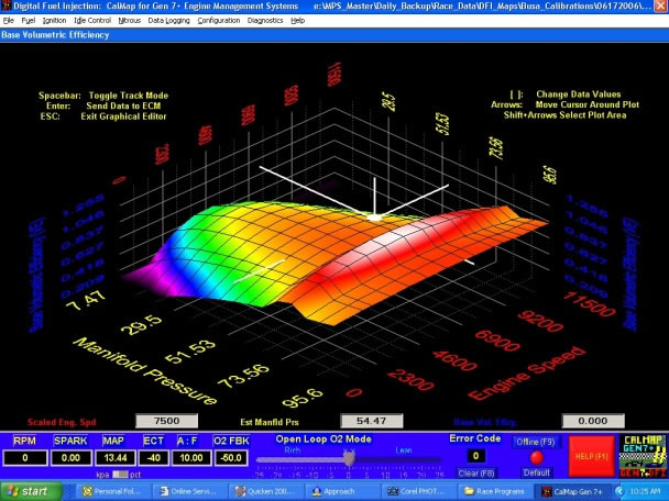 |
Graphical 3D fuel map |
Reading a Fuel Map
The axis on the right is RPM. The axis on the left is engine load. For naturally aspirated engines, the engine load is typically the same as the TPS (Throttle Positioning Sensor) reading, which is essentially how much throttle the driver applies. With pedal position changes, manifold pressure changes, measured in Kg/cm2. For turbo or other forced-induction engines, the engine load is typically the same as the Manifold Absolute Pressure (MAP) reading, which represents the vacuum or boost pressure of the engine. The mountain visible in the 3D representation is how much fuel the ECU is delivering to the engine, or the volumetric efficiency.
|
Numerical fuel map |
The image above shows a typical numerical two-dimensional map for a 1995 Mitsubishi 3000GT VR4 Spyder, with load (torque) on the vertical axis and RPM on the horizontal axis. The numbers represent the duration of injector opening or actual consumption. When choosing a value from any of the fuel or ignition tables, the ECU interpolates between the currently used cell and surrounding cells to ensure smoothness. In a fuel map, fuel consumption (g/kWh or g/s) is expressed as a function of engine speed and engine torque.
Coverage and Purpose
Fuel maps cover the entire engine working area, from idling speed up to maximum RPM and from full engine braking (negative torque) to full load. The main purpose is to tune the engine for all possible situations and allow it to run at its optimum level and highest potential at each combination of load and RPM.
Engine Tuning
Tuning the engine to achieve maximum efficiency is a significant part of extracting the best performance from a race car. Adjustments to the fuel injection system – changing the amount of fuel, injection timing, and utilising many available engine sensors – can all have a major impact on engine horsepower and efficiency.
The Role of Sensors
Sensors located in the engine and throughout the vehicle send information to the ECU, which interprets this data and uses it to keep the car working at its best. Key sensors include:
- Mass Air Flow (MAF) Sensor – measures the amount of air entering the engine. Less air is drawn in during idling, so less fuel is needed; at higher RPM, more fuel is required from the injectors.
- Oxygen (O2) Sensor – located in the exhaust system, it detects the amount of unburned oxygen so the ECU can adjust the fuel quantity to burn all available oxygen and increase efficiency.
- Throttle Position Sensor (TPS) – tells the computer how hard the driver is pressing the accelerator. The further and faster the pedal is pushed, the wider the throttle opens, increasing the amount of fuel required.
- Manifold Absolute Pressure (MAP) Sensor – measures changes in engine manifold pressure, telling the ECU how much load the engine must bear and how quickly it needs to respond. Higher pressure results in more fuel; lower pressure results in less.
- Vehicle Speed Sensor (VSS) – tells the ECU how fast the car is moving so fuel delivery can be adjusted accordingly.
The fuel map within the ECU adjusts the air/fuel mix for maximum efficiency and performance in any condition, provided the sensors are providing correct information.
ECU Control and Injection
All of these sensors and parameters are managed by the car’s ECU, which incorporates a fuel injection control system. This system sends signals to the fuel injectors, indicating when to open and how long to remain open to achieve maximum efficiency. Fuel is added to the air mixture at the latest possible moment before combustion. The ideal air-to-fuel ratio, called the stoichiometric value, is 14.68 parts air to one part fuel (AFR of 14.68:1 by mass). This is the ratio that allows oxygen and fuel to burn completely. However, conditions are never ideal, so the most efficient AFR depends on temperature, engine RPM, and engine load. The ECU receives and processes data from many sensors to make constant small corrections and optimise engine performance. The ECU also sends a signal to the spark coil so that it fires at exactly the right time to ignite the fuel, generating the high voltage needed to create a spark in the spark plugs, which in turn ignite the fuel-air mixture.
Using this data, different tables including volumetric efficiency and ignition advance can be created and adjusted to achieve maximum horsepower.
The Mapping Process
Fuel injection mapping is the process of systematically adjusting the fuel/air ratio at all operating points of the engine under specific conditions. For a normal road car user, the objectives might be emissions compliance, fuel economy, or a compromise between performance, emissions, and noise. For racing, there is no compromise – the sole focus is on power and torque. The mapping results would differ considerably between these applications.