Splitter and Air Dam

What Is a Splitter?
Front splitters are essential aerodynamic components that serve to balance the front vs. rear distribution of downforce. A splitter is typically found on the front end of a race car, appearing as a flat extension to the very bottom of the front bumper. This splitter extends straight out, parallel to the ground, and can be made of carbon fiber or other stiff material.
|
| ||
NASCAR type splitter | |||
It is attached to the bottom of the front bumper and may also be supported by two or more support rods at some distance forward of the bumper mounting points. These support rods ensure that the splitter stays parallel to the ground, even when outside forces act around the splitter.
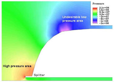
Front-end splitters on a race car produce aerodynamic downforce by creating a difference in air pressure on the upper and lower sides of the splitter when the car moves.
The Aerodynamics of a Splitter
To understand how a splitter creates downforce, a basic knowledge of fluid dynamics is necessary. One should at least be aware of the difference between static pressure and dynamic pressure. It is also instructive to know how dynamic pressure is related to flow velocity. This relationship is given by the well-known Bernoulli equation. Though Bernoulli’s principle is a major source of lift or downforce in an aircraft or racing car wing, the Coanda effect plays an even larger role in producing lift.
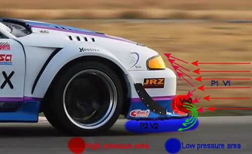
When a car travels at high speeds, the air pressure in front of the car can become very high. The incoming air approaches the car at velocity V1, which is the speed of air around the vehicle, and a pressure P1 which is related to V1 according to Bernoulli’s equation. P1 will be somewhat less than atmospheric. The essential point to be taken from Bernoulli’s equation is that the pressure inside an airstream is related to the velocity at which the airstream is moving.
All this air ends up going both above the car (over the hood) and below the car (under the front bumper). When too much of this air gets under the front bumper, the under-car air pressure builds up. This increased air pressure contributes to lift, which causes the front end of the car to lighten, reducing the amount of traction at the front. This high-pressure (and lower-speed) air, when compared to the air speed above the car, creates a situation where there is increased lift over the entire car. Typically, most production street cars travelling at higher speeds (100 km/h and above) produce large amounts of positive lift.
The desired outcome is lower-pressure, faster-moving air below the car, and higher-pressure, slower-moving air above the car. The lower-pressure side, when it happens to be under the car, contributes to reduced lift. When the lift is reduced sufficiently to the point where there is negative lift, there is net positive downforce.
As the airstream velocity goes up, the dynamic pressure within the air goes down. In simple terms, the air travels faster in the low-pressure area created under the splitter, and that “sucks” the car’s nose down, creating downforce and reducing understeer, especially on a track with fast flowing corners.
How the Splitter Works
The splitter itself does not actually create downforce directly. What the splitter does is increase the area over which high pressure can build up. The more high pressure there is above the splitter, and the more low pressure there is below the splitter, the greater the net downforce. Additionally, if there are openings in the front bumper (above the splitter or lip) for brake ducts or radiator cooling, this increased air pressure will encourage more air to flow into these openings.
The drawing above shows what happens when incoming air reaches the front of the vehicle. The air must come to a stop before it turns to move either up and over, down and under, or around the vehicle. The area where the oncoming airflow comes to a stop is termed the “stagnation point,” since the velocity has gone down and the pressure has gone up (the “stagnation” pressure). In other words, the front of the moving vehicle is an area of relatively high pressure.
The lower the car is to the ground, the greater the suction created by the ground effects, and therefore the splitter is usually located at the lowest possible point.
Ride Height Sensitivity
However, if the splitter is too close to the ground, it will stall, producing less downforce and more drag (exactly the opposite of what is desired). This occurs because air cannot pass through the bottom part of the splitter, so the speed of the flow there decreases, increasing the pressure. From this it is clear that a splitter can be very sensitive to ride height. In order to remove this sensitivity, different heights on the splitter can be used – in other words, an anhedral shape. This solution has the advantage that if the car touches the ground, part of the splitter will continue to create downforce.
If a heavy front-engine car is prone to understeer, apart from reducing weight, upgrading the suspension, widening the wheel track, and adding fatter rubber up front, a splitter can be incorporated to help eliminate understeer.
| |
|
Basic Splitter Design
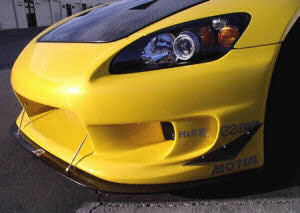
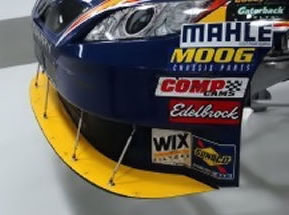
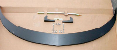
The shape and design of the splitter is straightforward – it is essentially a half-moon-shaped flat sheet that fits horizontally under the car. The pictures here show a basic NASCAR splitter and an aftermarket Ford Mustang splitter.
More sophisticated racing classes naturally have more sophisticated splitters.
|
|
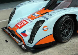
| Here we can see front splitters of Audi R8, Aston Martin Lola Le Mans 2009 and Audi R15 Le Mans 2009. We can see that on Audi R15 Le Mans, splitters are integral part of front wings assembly. A lot of the people will say: "Hey, there is no splitter, only front wing" but that's not a case! What we can see on Audi R15, is more splitter than the wing, and all of this is part of front diffuser. |

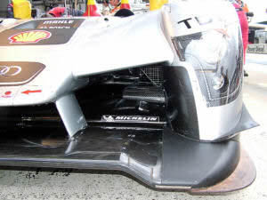
The splitter seals off the entire area from the front of the vehicle to just short of the front wheels. This creates a decent low-pressure area under the car to assist downforce, but only at speeds above around 120 km/h. In slower corners the car still relies on mechanical grip – stiffer suspension and wider rubber do the job. The splitter adjusters must be lightweight and spring-loaded.
Materials and Construction
To construct a strong and flexible splitter that can withstand accidental bumps, multiple layers of composites can be incorporated – Kevlar for flexibility, overlaid with carbon fiber for strength – but the cost can be prohibitive. 8 mm plywood or fibreglass composite works just as well and makes surprisingly lightweight splitters for a fraction of the cost.
If a mishap occurs during Friday practice and the front splitter needs replacing, Kevlar and carbon fibre are unlikely to be found at the local hardware store.
Splitters on Street Cars
It is worth noting that a splitter is aerodynamically effective only at speeds above 120 km/h. For a car used for everyday commuting, the aerodynamic advantages of a splitter are rarely exploitable.
|
|
|
|


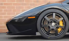

Consider the ground clearance on a street-legal Ferrari F430 Scuderia, Hamann-Lamborghini Gallardo, or Lotus Evora (clockwise). The designers gave careful thought to the front-end and splitter design on these extreme sports cars. Note how low the car sits, but even with such little ground clearance, the stock spoiler is relatively safe from unexpected speed bumps and curbside parking. The splitter does not protrude excessively.


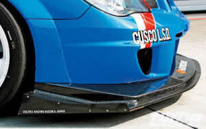
The picture on the left illustrates the lack of ground clearance with a lowered ride height and a splitter mounted far ahead of the front wheels. A closer look reveals that the bottom of the spoiler would hit the tarmac on speed bumps or during curbside parking.
For a splitter, a general guideline is that it should be twice as long as the ground clearance to be effective. So if the bumper is 5 cm off the ground, the splitter needs to stick out 10 cm. Such setups can be dangerous and possibly illegal on street cars.
Radical front spoiler setups with minimal ground clearance on road cars are a legitimate safety concern. Striking an object at the wrong angle could force the spoiler under the front wheels, causing a complete loss of control.
What Is an Air Dam?
What is an air dam:
An air dam (also known as a “front air dam”) is usually a shaped part of the lower portion of the front bumper. It is sometimes called a “front lip” or “lip spoiler.” It can be moulded as part of the front bumper, or it can be a separate part attached at the front-lower portion of the front bumper. Unlike the splitter, the lip is not a flat “sheet” of material. The function of both is the same – to create lower and higher pressure areas – but in the case of an air dam, in a less extreme way.
Splitter in Formula 1
The Formula 1 splitter is known by many names, such as the shadow or legality plate, T-tray, or bib. The T-tray or splitter is the flat area that the plank or skidblock is attached to and stretches out at the front underneath the raised nose area of the car.
In the late 1980s, when designers were slimming and raising the nose of the cars, there was a need to create a floor section under the front of the monocoque to meet the flat-bottom rules. The first splitter used in Formula 1 was on the Tyrrell 019 with its fully raised nose. Since then the spli
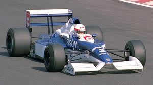
tter has been more and more exposed as teams seek to raise and narrow the chassis cross section for aerodynamic benefit.
Aerodynamic and Structural Role
The Formula 1 splitter’s regulatory role has been to form the flat bottom of the car and provide an attachment for the plank running along the length of the flat floor. The splitter must form the flat floor at reference plane level. The splitter must also shadow the plan profile of the monocoque, such that the monocoque cannot be viewed from beneath the splitter. The original intention of the FIA was only that.
However, as with everything in Formula 1, this bodywork forming the floor has been exploited and the splitter now performs aerodynamic and chassis functions of its own. As the term suggests, the splitter separates (splits) the airflow passing under the raised nose into two separate flows – one passing above and one passing below the floor. On the upper part of the splitter, at the point where it meets the monocoque, there is a bow shape. This “shape” also splits the airflow passing over the floor between left and right. Air spills under and over the splitter.
Teams make use of this powerful flow to alter the air pressure distribution across and over the underfloor to further improve airflow through the diffuser. Together with fences, vortex generators, and previously bargeboards, the splitter forms a critical role in the onset flow for the diffuser.
|
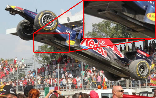
GP of Monza 2011 footage of the Mark Webbers Red Bull being lifted on a crane over a spectator area |
Ballast Placement
Being mounted low and far forward, the splitter also provides a good location for ballast. Depending on the prevailing tire and aerodynamic requirements, teams can run as much as 50% of the car’s weight on the front axle. With a rear-engine car, the only way to achieve this is to ballast the front of the car, and the splitter has been known to be made entirely from metal in order to maximise front-end weight bias.
Movable Floors
Since the 2007 season-opener in Australia, there has been much discussion of ‘movable’ floors on Formula One cars. Teams have developed ways to mount the splitter so that it will pass the standard deflection test during scrutineering, but then lift under greater aerodynamic loads at speed on the circuit, providing significant aerodynamic gains.
If the car’s bib is allowed to lift at high speed, it leads to stall of the underbody aerodynamics. That means that the airflow passing through the diffuser no longer closely follows the diffuser’s profile. Instead, at a certain point – determined by air pressure levels close to the diffuser wall – the airflow detaches and proceeds on its own horizontal trajectory. This leads to less drag with less downforce. More about movable floors can be found in the article here.
Regulatory Requirements
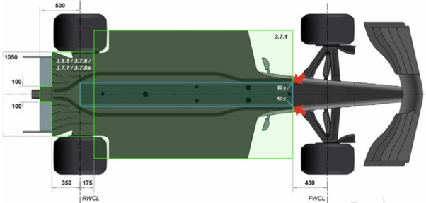
F1 rules deem that the front area of the splitter (T-tray, bib) needs to be shaped in a certain way. Article 37.1 states that the surface formed by all parts lying on the reference plane must: “Have a 50mm radius (+/-2mm) on each front corner when viewed from directly beneath the car, this being applied after the surface has been defined.” The image below from the FIA rule books makes clear where the 50 mm radius needs to be.
History of the Air Dam/Splitter in Formula 1
For most of the 1970s, there were two fundamental schools of thought about front-end aerodynamic concepts on Formula 1 cars.
|
Nose cone of BRM P160, Tyrrell 006 and Mclaren M19 |

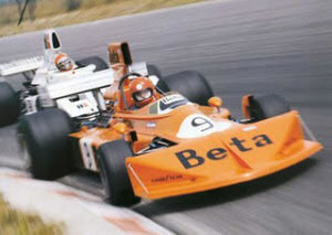
Some of the cars, such as the McLarens, Lotuses, and Ferraris, continued to run with front wings, but another group appeared to abandon that concept for most of the decade, running instead a front air dam/splitter. This latter group included teams such as March, Brabham, and Tyrrell, with Jackie Stewart winning the 1971 and 1973 World Championships in Tyrrell designs with just such a front-end configuration.
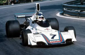
So what was the idea? Part of the motivation was presumably to reduce the lift, drag, and turbulence created by the front wheels. The front spoilers were much wider than front wings, and partially shrouded the front wheels, diverting airflow over and around the wheels.
The other possible motive is perhaps more interesting, because it involves ground effect.
An air dam/splitter provides a vertical barrier which:
Maximises the high-pressure stagnation point at the front of the car, and
Accelerates the airflow through the restricted gap between the air dam/splitter and the ground surface.
A horizontal splitter extending from the bottom of the air dam/splitter then takes advantage of the high pressure of the stagnation point to generate some extra downforce.
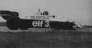
A front air dam/splitter is partially, then, a ground-effect device, which perhaps explains why cars such as the Brabhams and Tyrrells were still able to win Grands Prix against those utilising conventional front-wing arrangements. The photo here shows a Tyrrell 6-wheeler running quite a degree of rake, which would serve to accentuate the ground effect of the front spoiler.
So, perhaps surprisingly, ground effect in Formula 1 actually predates the underbody venturi tunnels and skirts used on the Lotus 78/79. Gordon Murray began experimenting with ground effect on the Brabham BT44 back in 1974, arriving at “an inch-deep underbody vee, something like a front airdam, but halfway down the car.”
The introduction of underbody venturi and skirts presumably spelled the end for front spoilers, as the emphasis then shifted to feeding the underbody with as much airflow as possible.