Flow Visualisation Paint (Flow-Viz)
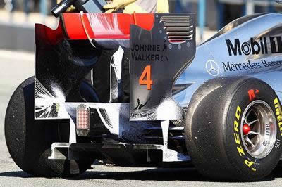
McLaren using Flow-Viz paint at preseason testing at Jerez 2011
Introduction
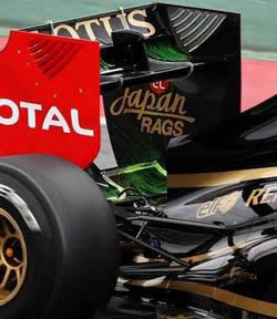
When McLaren ran flow-viz paint on their car for the first time during testing in 2010, the F1 world saw the technique openly for the first time. In reality, teams had been using this method for years in the privacy of their wind tunnels to visualise surface aerodynamic flows. By 2011, Renault, Lotus, Red Bull, and Ferrari had also brought it to the track, and large amounts of green, blue, or white fluid were openly splattered over the cars.
Purpose and Limitations
There is no mystery to the technique. It involves a special liquid placed onto the car to assist with aerodynamic analysis. Engineers recognise that work in the wind tunnel and CFD programs can deliver excellent results, but nothing compares with real-life conditions on the track. To better understand airflow over aerodynamic surfaces in this environment, teams employ what is called flow-viz paint, or flow-visualisation paint. Details such as flow direction and whether flow is attached or separated can be observed. However, this only reveals surface airflow, which is not the entire aerodynamic picture, so flow-viz is just one tool for measuring and observing aerodynamics on the track.
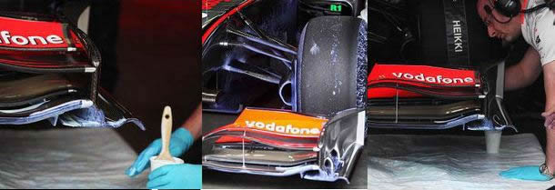
McLaren engineer applying Flow-Viz paint on front wing
Application and Use
The paint is applied, and before it has a chance to dry the car is sent out around the circuit. As the car circulates, the airflow moves the paint, which then dries in place, revealing detailed airflow patterns across the car. The primary purpose is to confirm wind tunnel and CFD findings.
Formula 1 teams do not like to use this method frequently because it exposes their aerodynamic characteristics to rival teams. If a team has an aerodynamic problem, everyone can see it; if there is an innovative airflow management solution, everyone will know about it. A simple photograph analysed by a rival aerodynamicist can reveal significant information. A team resorting to flow-viz paint so openly, in front of so many observers, typically indicates either genuine aerodynamic problems or fundamental development work in progress.
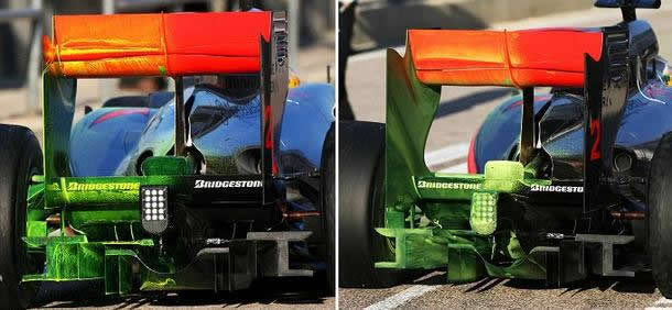
|
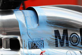
McLaren duringF-Duct testing 2010. You can clearly see slot in rear wing flap on picture above, and air streams around it. |
Composition
The paint is a paraffin-based light solution applied to the car. The solution is light enough to flow over the car while drying quickly, allowing the airflow over the bodywork to be determined.
A component surface is coated with a pigmented (preferably a contrasting phthalocyanine) or transparent oil-based paint of non-gelling characteristics, with a specific viscosity chosen so that the paint will not move when the car is stationary. If a team needs to run a longer stint with flow-viz applied, an additional layer of wetting agent can be applied to prevent premature drying. Particles of a dry phthalocyanine dye are then uniformly sprinkled onto the paint coating using a dry brush or an air blower, depending on the accessibility of the surfaces under test. Dye particles must be soluble in the oil-based paint. Optionally, a wetting agent such as linolic acid can be applied to ensure cohesion of the oil-based paint and dye. After application, the car goes out on track to pass an airflow over the components.
How the Patterns Form
As the airflow passes over the component, it causes the dye particles to move across the paint coating. The particles dissolve in the oil as they travel, leaving a trail on the surface. This results in a reduction in particle size due to dissolution. The airflow produces a pattern of contrasting trails on the surface of the coating, permanently recording the fluid flow distribution for later analysis.
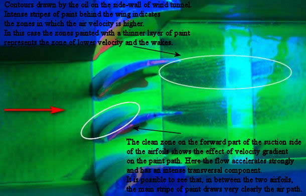
Comparison of the relative movements of the dye particles provides an indication of the relative strengths of the airflow acting on the surface. An aerodynamicist can read the contours drawn by the oil on surfaces such as the rear wing support or the wing element itself. Intense stripes of coloured oil behind a wing cascade indicate zones of higher velocity.
This occurs because oil flowing from upstream feeds the wing element downstream. Zones painted with a thinner layer of oil represent areas of lower velocity and wakes. The clean zone on the forward part of the suction side of the aerofoils shows the effect of the velocity gradient on the paint path, where the flow accelerates strongly and has an intense transversal component. Between the two aerofoils, the main stripe of oil draws a very clear path of the air.
By examining the oil stripes on tested elements, engineers can determine whether the flow trajectories match the CFD simulations or wind tunnel test results.
Real-World Examples
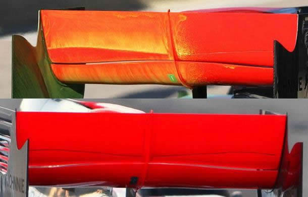
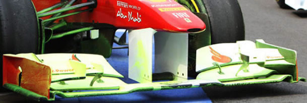
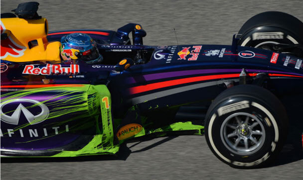
The photograph below was taken during Saturday morning practice at the Korean Grand Prix 2011, as Ferrari tested a new front wing planned for the following season with flow-viz paint sprayed over it.
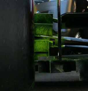
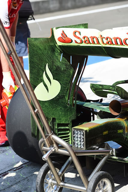
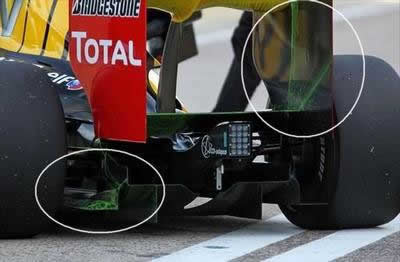
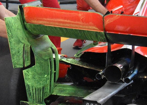
A close look at this rear brake duct on the Marussia car during the 2013 preseason test in Jerez reveals a component known as a cascade – a multi-element piece on the brake duct that serves as an important downforce-generating device close to the rear wheel.
The flow structure is visible: the lower lines are not too bad, but as the upper elements are reached, the flow moves inboard and separates at the top edge, and on the top element the flow has broken down completely.
This cascade is not working properly; the geometry is too aggressive, and the imperfect flow lines are a clear indication to the team’s engineers that further wind tunnel work is needed. The lines of paint should be smooth, with the air remaining attached as it works its way over the tested piece – that is what engineers want to see when they analyse the flow structure. It means the element is performing as expected.
Ferrari SF15-T rear wing with flow-viz applied