Courtesy of:
Willem Toet, Head of Aerodynamics, Sauber F1 Team, Sauber Motorsport AG
Surface Finishes – Why They Are Not Used on an F1 Car
Introduction
Aerodynamicists are frequently asked about ways to improve the performance of race cars using golf ball dimple effects, shark skin, riblets, super-smooth surface finishes, bumble bee effects (hairy surfaces), and similar approaches. This question arises so often that this document has been dedicated to explaining some of these effects.
| 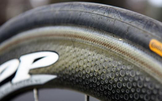 |
Zipp Speed Weaponary, one of the world’s market leaders in racing bicycle wheels hold the world patent on dimpled disc cycle wheels, and they seem to work, being chosen by a number of top teams including some Tour de France front runners. Zipp use a roughly meniscus-shaped dimple with a flat bottom that sweeps upwards near the edges. Apparently this shape is popular in current golf ball design, particularly with manufacturer Titleist. |
Businesses exist – and some even thrive – on the promise of improved downforce/lift or reduced drag, or sometimes both, using surface-finish-related treatments. Surface finish is important, but not as fundamental to race car performance as some proponents suggest. For certain objects operating at different speeds and with different shapes, the importance can be much greater: a human swimmer, runner, or cyclist (at low speeds) or an aircraft (at high speeds where skin friction drag dominates). For different reasons, surface finish can be very important in these cases.
Flow States on an F1 Car
F1 cars operate with many different flow states, including the following:
Laminar (efficient, powerful, ideal but potentially unstable and rarely sustained for any length of surface on an F1 car – due to surface imperfections from running many laps in the real world, the extreme shapes employed to generate downforce, following other cars, etc.). Catastrophic flow separation is possible directly from laminar flow regions, and laminar flow is easily disturbed by surface imperfections.
Transition to turbulent (less efficient in theory but more stable or more likely to remain attached to a curving surface). As turbulent flow is pushed further, a separation bubble may begin to form (implying the flow reattaches further along the body). Sometimes off-body separations appear in the flow region while the flow still appears to be just attached on the body surface.
Asymmetric 3D flow – remaining surface flow begins to go asymmetrical and move sideways relative to the global airflow direction. This typically occurs because one of two vortices has burst, and some separation usually exists adjacent to the asymmetric flow.
Full separation of the flow from the body.
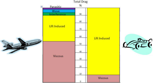
|
Fig 1. Comparison of total drag of a plane vs an F1 car * |
The Golf Ball Dimple Effect
The impact of golf ball dimples is the primary focus here, but understanding this effect makes it faster and easier to understand the impact of other surface treatments. The same concept of dimples is also used on some other sporting goods where it can make a meaningful difference.
To explain the effect, some basic principles are necessary. All other things being equal, the aerodynamic drag of an object increases with the square of speed (twice the speed means four times the drag force).
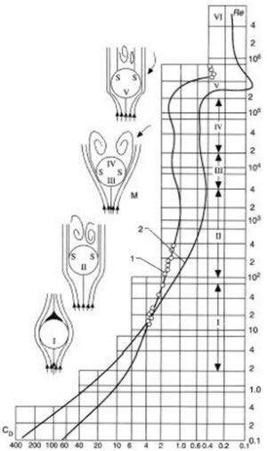
|
Fig 2. Drag coefficients for cylinders (1) and spheres (2) as a function of Reynolds number (Re)** |
Drag Coefficient and Reynolds Number
For this reason, many objects (including cars) are often characterised by a drag coefficient or the drag coefficient multiplied by the frontal (cross-sectional) area. For simple comparisons, these numbers can indicate which body has more or less drag.
However, the drag coefficient of an object does not always remain the same as speed changes, especially at quite low speeds, for small objects, or at very high speeds (approaching the speed of sound). These changes in drag coefficient occur because the behaviour of air changes as speed and size vary. Aerodynamicists use Reynolds numbers – a non-dimensional number (essentially speed multiplied by fluid density multiplied by the length of the object, divided by the viscosity of the fluid) – to understand boundary layer behaviour and flow types around a body.
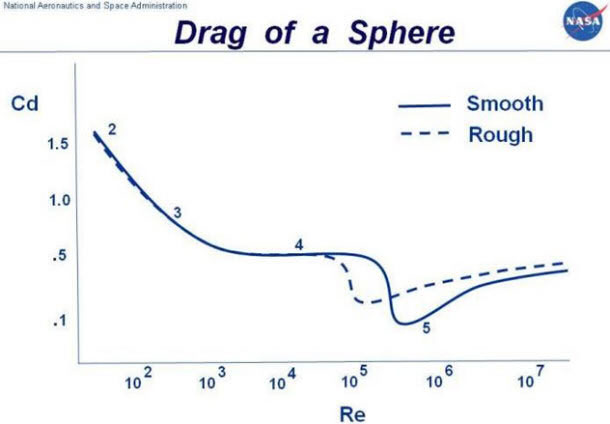
Golf balls have been scientifically compared to smooth spheres in numerous studies. From the data, the drag of smooth and rough spheres crosses over as the Reynolds number changes. At certain speeds, the smooth sphere has less drag; at other speeds, the smooth sphere has more drag. The difference can exceed 25% of the drag of the object under given conditions.
|
Fig 3. Plot of drag coefficient v Reynolds number for a smooth and rough surface sphere (courtesy of http://www.grc.nasa.gov/WWW/k-12/airplane/dragsphere.html) |
Shape vs. Surface Finish
For comparison, going from a cylinder to an aerofoil, the drag (again depending on speed and scale) drops from a coefficient above 1.0 for the cylinder to less than 0.1 for an aerofoil called a NACA 0030. This over-90% reduction makes a 25% reduction in drag
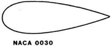
seem small by comparison. Suspension elements on Formula 1 cars are regulated to have maximum aspect ratios somewhat like this sketch. This means that for a car designer, thinking about global shape changes is likely to be more productive in terms of drag reduction than experimenting with special surface details. Aerodynamicists in both the aircraft and automotive industries quickly realised, after early experiments, that working on overall shape was more productive than experimenting with surface finishes. In normal operation on a road car, skin friction accounts for no more than 1% of the total drag, since the main drag generation mechanism is the vehicle shape. Ford experimented with shark-skin wrapping in the mid-1980s when they developed a low-drag Probe IV concept car with a Cd of 0.15. They did not see improvements in drag, so they moved on to work with the vehicle shape. ***
Why Dimples Work on Blunt Bodies
| 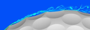 |
High performance computing can be used to address important problems related to science and engineering but also for fun. Here was used parallel Navier-Stokes solver to compute the flow around a golf ball traveling at speeds up to 100mph. The computations are amongst the largest Direct Numerical Simulations of complex flows ever performed, involving billions of grid points and thousands of processors on large parallel clusters. Our aim is to illuminate the detailed mechanisms by which the dimples dramatically reduce the drag force on the golf ball over a narrow range of speeds.Collaborators: K. Squiers, M. Tsunoda From: http://www.seas.gwu.edu/~balaras/index.shtml |
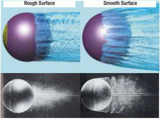
The most effective way to reduce drag on a golf ball is to trip the boundary layer. This is done by using dimples – creating a rough surface that promotes an early transition to a turbulent boundary layer. This turbulence helps the flow remain attached to the surface of the ball and reduces the size of the separated wake, thereby reducing the drag generated in flight. When drag is reduced, the ball flies farther.
The best way to reduce drag on an object also depends on the degree of control that can be imposed on the direction of airflow. For an aircraft or a car, airflow direction can, to a greater or lesser extent, be predicted. Extremes of crossflow or reverse flow are not frequent, so they are not given the same weight in performance optimisation.
|
Fig 4. Comparison of flow separation and drag on blunt and streamlined shapes |
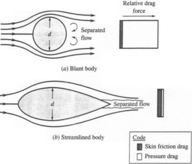
The reason dimples are not seen on other shapes, like wings, is that these particular forms of boundary layer trips only work well on blunt bodies like spheres or cylinders. The most dominant form of drag on these shapes is pressure drag. More streamlined shapes like the aerofoils used on wings are dominated by a different kind of drag called skin friction drag. These streamlined bodies have a teardrop shape that creates a much more gradual adverse pressure gradient. This less severe gradient promotes attached flow much further along the body, eliminating flow separation or at least delaying it until very near the trailing edge. The resulting wake is therefore very small and generates very little pressure drag.
Vortex Generators on Wings
However, there are other types of devices commonly used on wings that create an effect similar to the dimples on golf balls. Though these wing devices also create turbulence to delay flow separation, the purpose is not to decrease drag but to increase downforce. One of the most popular of these devices is the vortex generator. Vortex generators are often placed along the outer portion of an aeroplane wing to promote a turbulent boundary layer that adds forward momentum to the flow. As with the golf ball, this turbulent boundary layer helps the flow overcome an adverse pressure gradient and remain attached to the surface longer than it would otherwise. ****
F1 Aerodynamic Complexity
For global vehicle performance reasons, all front wing shapes used in F1 are almost brutally three-dimensional – the shape is different as one moves along the span. These shape changes create vortices at profile junctions, which need to be managed as they move along and around the car. F1 teams employ a number of aerodynamic devices that make virtually no direct contribution to downforce but that create or manage flow features around directly important downforce-generating surfaces, thereby enhancing overall performance. *****
It should also be remembered that, during a race, an F1 car is bombarded with sand, stones, insects, balls of rubber, and other debris that can noticeably change car performance.
Sauber’s Experience
A significant amount of research would be needed to determine if and where different types of surface finish might improve a car. Past experience, including short-term positive results with surface finish changes, has shown that revising the shape was more effective than revising the surface finish. Covering an entire vehicle with any single treatment would be neither practical nor beneficial. Investment in this research was made in the past and again in 2012, but it did not lead to an improvement. From time to time, new information suggests there may be a chance to improve performance in this way. However, no permanent improvements have yet been found using this technique. Most teams in F1 have had the same experience as Sauber.
Willem Toet
February 2013
References
There are many references relating to this subject available on the internet. Some have been used in the creation of this document.
REFERENCES:
- Schrauf, 2005
** Polezhaev, Yu.V. & Chircok, I.V., “Drag Coefficient”, DOI: 10.615/AtoZ.d.drag_coefficient, Fig 1, Thermopedia, http://www.thermopedia.com/content/707/?tid=104&sn=1423
*** Bill Pien, Supervisor of Aerodynamics in Ford Vehicle Engineering, October 2009, http://www.popularmechanics.com/cars/news/4316702
**** Jeff Scott, 13 February 2005*,* http://www.aerospaceweb.org/question/aerodynamics/q0215.shtml; http://www.aerospaceweb.org/about/bios/jeffscott.shtml
***** Toet, W., Aerodynamics and Aerodynamic Research in Formula 1, The Aeronautical Journal, 117, No 1187, January 2013