Diffuser
Introduction
Once the potential of using aerodynamic downforce to win races was realised, designers began experimenting with methods other than simply attaching inverted wings.
The diffuser is an area of bodywork at the rear of the car. Although the term “diffuser” is technically not entirely accurate, it is the most widely used name for this part of the car.
The air flowing below the car exits through the diffuser at the rear. The diffuser is usually found on each side of the central engine and gearbox fairings and is, by regulation, located behind the rear axle line. The diffuser creates nearly 50% of the car’s downforce. Being so powerful, the rules have progressively been tightened, making the diffuser smaller and smaller to cap cornering speeds.
How the Diffuser Works
Although wings and diffusers work similarly, they are based on different concepts. A diffuser serves to eject air out from the underside of the car. This pulling action increases the velocity of the air below the car, so that the more slowly moving air above the car pushes the car into the ground. The suction effect is a result of Bernoulli’s equation, which states that where the speed of a fluid is higher, pressure must be lower. Therefore, the pressure below the race car must be lower than the pressure at the outlet, since the speed of the air below the car will be higher than the speed of the air at the outlet.
The diffuser in itself does not produce a reduction in pressure. The role of the diffuser is to expand the flow from underneath the car to the rear, decrease the flow’s velocity from inlet to outlet (so that at the outlet the flow velocity is similar to the free-stream velocity), and in turn produce a pressure potential that accelerates the flow underneath the car, resulting in reduced pressure and an increase in downforce generation. This pressure difference is a function of the ratio of the areas at the inlet and the outlet of the diffuser, where this area ratio is set by the diffuser angle and the vehicle ride height.
The diffuser can be considered to have “pumped down” the underbody, inducing a component of downward force on the vehicle.
Three Mechanisms of Downforce Generation
Testing has shown that the diffuser actually acts as a pump to generate downforce over the underbody flow path. This is not the only identifiable fluid-mechanical mechanism affecting the flow path around the diffuser. The three main aspects are: “ground effect”, “underbody upsweep”, and “diffuser pumping”.
“Ground Effect” plays a role when an object is used in the vicinity of a moving ground. Flow asymmetry develops from the flow accelerating as it travels underneath the body due to ground constraint. As a result, the static pressure underneath the body is reduced, which provides the resulting downforce.
“Underbody Upsweep” refers to the upsweep of the diffuser at the rear. This is typically cambered and up-curved in shape, similar to the upper surface of an airfoil. Due to the direction of this curving, a resulting downward-directed lift force is produced during flow interaction.
“Diffuser Pumping” refers to the increased cross-sectional area over the diffuser length, which can be used to increase the flow rate through the diffuser because of pressure potential. As the ratio of the inlet to outlet area becomes increasingly greater, this generates greater pressure recovery that, due to the base pressure remaining constant, increasingly depresses the base pressure at the inlet. The diffuser acts to reduce the underbody pressure due to the expansion, resulting in increased flow rate under the body. This increase results in further decrease in underbody pressure, which produces the “pumping down” effect. This scavenging both produces a lower pressure area under the car and also acts to reduce the boundary layer. This effect is reduced at the higher underbody heights regulated since the 1990s.
|
|
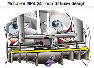
Diffuser design before 2009 rule change | |
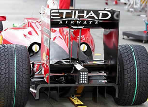
Diffuser Design Details
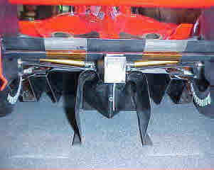
The design includes vertical fences, some of which are curved, some stepped, and some angled, but all developed through constant tweaking and evolution in the wind tunnel. The basic job of these fences is to keep apart the many different types of airflows found at the rear end of a racing car – areas of low-pressure air due to the rear wheels and the rear wing, and the air coming under the floor. All these different airflows have different energy levels and different speeds, and their separation makes them easier to manage.
Showing precious little of the secretive diffuser, F1 rules prohibit under-car shaping or venturis and mandate a minimum ride height enforced by a relatively low-tech wear plank or skidblock attached underneath the car. However, there is still scope to shape the area directly under and behind the rear axle line.
Diffuser on Mercedes GPW01 formula 1 car
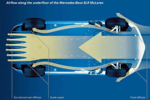
Front Underbody Diffuser
Front Underbody Diffuser
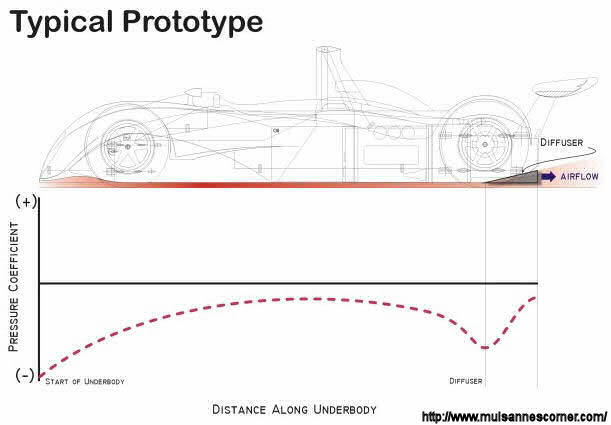
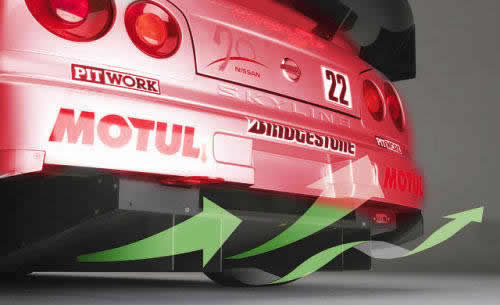
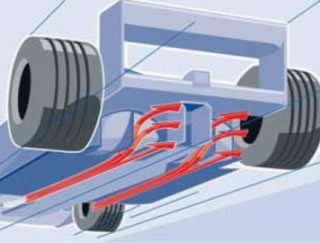
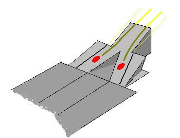
Here we can see a typical diffuser on prototype LMP car. They have one more “diffuser” area below the nose of the car. We can see building up of the negative pressure in these two areas
LMP cars have a flat bottom, but the front of the car can have ducts to feed the engine and related systems. These ducts are also used to gain additional downforce. As can be seen in the image of a Toyota GT-One undertray, the front part of the undertray is highly contoured, so that air coming under the car splits: some goes through to the rear of the car, while another portion exits behind the front wheels. This flow goes upward into a diffuser-like compartment where its pressure is reduced, thus generating downforce just ahead of the front axle. The effect is essentially the same as an air splitter, but here the flow is also directed towards the sides and the splitter that marks the beginning of the flat floor.
Looking at the diagram, it can be seen that the car’s front is very similar to a wing in ground effect, even though looking at the vehicle there is no wing present. This design is not as effective as a “real” wing due to the redirection of flow. However, the fact that the sides are relatively sealed increases the effect of the shape.
There are different ways of handling the airflow in the front of the car. Here, the designers are trying to achieve the same thing as in the rear diffuser: more front-end downforce by giving the air a place to expand and thus reduce pressure.
Diffuser Stall
Diffusers, when well designed and working properly, can be extraordinarily important to the aerodynamics of a car. The diffuser, combined with the airfoil in the lower portion of the rear wing, produces significant downforce – approximately 40 to 50% of the total car downforce. When not working properly, a diffuser can trouble even the most experienced drivers.
A common problem for some badly designed diffusers is known as “diffuser stall.” Sometimes the problem with the diffuser stalling is linked to poor design of the front wing.
Every team’s diffuser will stall to some degree when the rear of the car, because of high speed and higher downforce, is closer to the ground, which reduces drag and allows higher top speeds. But this also reduces downforce, and it is vitally important that the airflow reattaches the moment the rear of the car starts to rise. Otherwise, the braking zone becomes problematic for the driver.
If a driver believes there is a certain grip level while taking a corner, the car will be taken at the highest speed possible assuming this level of grip. While braking, the car pitches forward. This forward pitch lifts the rear of the car. If not designed properly, a diffuser will lose a very large percentage of its effectiveness if lifted even a small amount (with the stiffness of F1 suspensions, this “small amount” is 5 to 10 mm). When this happens, a large amount of downforce is lost, and in turn a large amount of grip is lost. If most of the 40 to 50 percent of a driver’s aerodynamic grip is lost mid-corner, it is very difficult to keep the car from twitching, and on onboard TV the driver can be seen “hunting” the car with the steering wheel. To compound this problem, the diffuser sometimes does not reattach airflow effectively once it stalls.
Exhaust-Blown Diffusers
During the past, there were several ideas for improving diffuser efficiency. A well-known approach (though not the first attempt) was McLaren’s method of speeding up air exiting the diffuser by blowing high-speed exhaust gases inside the diffuser area to “energise” the flow. The speed of the airflow through the diffuser can be increased by the high-velocity gases exiting the exhaust pipes when the engine is revving. This apparently free increase in diffuser performance was very popular in the 1990s and was encouraged by bodywork restrictions preventing the exhaust pipes from routing over the gearbox. The high-velocity gases entrained air, energising the thick boundary layer, and effectively powering up the diffuser as it drew air under the car.
This idea was excellent but not very successful in practice. The problem was that exhaust gases do not have a constant speed. The more the driver presses the throttle pedal, the higher the speed of the exhaust gases and the better the diffuser efficiency. Less throttle means lower gas speed. With lower gas speed, diffuser efficiency drops, and driving the car with lower downforce at the rear is not pleasant. The worst part is that during cornering, when more downforce is needed, drivers usually need to lift off the throttle slightly, losing downforce at that critical point.
Slowly the practice was dropped, first by routing the exhausts into less effective positions in the diffuser and then through the top of the sidepods using the Ferrari-inspired “periscope” exhausts.
The teams need to leave a hole in the centre of the diffuser to insert the outboard starter mechanism, which usually results in small cut-outs in the lower ramp of the central part of the diffuser and in the vee formed above the shadow plate. The effect of this on diffuser efficiency is minimal.
Evolution: Double Diffuser and Blown Diffuser
Notwithstanding the 2009 downforce reduction rules, the diffuser continued to be the dominant factor in aero design. Making the most of creating low pressure under the rear of the car’s bodywork remained as important as ever. In 2009, teams exploited rule loopholes to create additional underbody inlets feeding larger exit areas, known as the double diffuser (more on that later in the article). In 2010, teams further exploited these rules for ever larger inlets and outlets.
However, it again fell to Red Bull’s Adrian Newey to look at the history book and re-invent a concept that had fallen out of favour. The previous year he had done this with the pull rod rear suspension, and in 2010 it was the exhaust-driven diffuser. By mounting the exhaust outlets in line with the floor, they blow through the diffuser, driving greater airflow and hence creating more downforce. Already with mid-season upgrades, many teams followed Red Bull’s lead. Read here how the blown diffuser works.
Though Bernoulli’s principle is a major source of lift or downforce in an aircraft or racing car wing, the Coanda effect plays an even larger role in producing lift. To know more about interaction of Bernoulli’s principle and Coanda effect, check my article here.
Sports Car Diffuser Examples
A few examples of sports car diffusers:
Ferrari Enzo front and rear diffuser
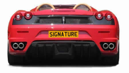
Rear diffuser on Ferrari F430
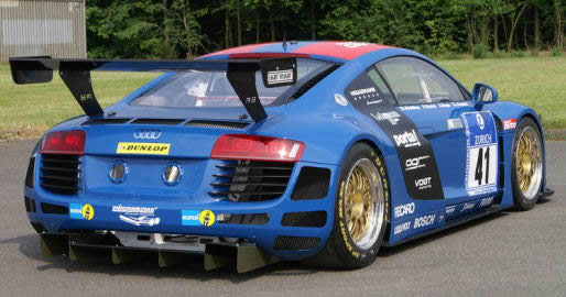
Rear diffuser on Audi R8 ready for DTM racing
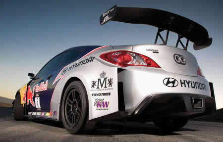
Diffuser on Hyundai Genesis Coupe D1 Drift car
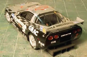
Rear diffuser on Shevrolet Corvette Can-Am
2009 Regulation Changes
The regulation changes for 2009
As part of the package of aero changes designed to reduce downforce for 2009, the diffuser underwent quite complex modifications. Moves to create a more standardised shape removed the difference in height between the central and two outer sections, and all three channels were now taller – 175 mm rather than 125 mm. In addition, the diffuser was moved rearwards, with its trailing edge now 350 mm behind the rear axle, compared with the previous arrangement where it was level with the rear axle.
|
|
Diffusers on Ferrari and McLaren 2009 designed by the letter of the new regulations | |
McLaren, Ferrari, Renault, and BMW Sauber all made very literal interpretations of the revised 2009 rules regarding the rear diffuser. All of the channels were the same height and length, with no difference in height between the main central section and the side channels.
This contrasted with the designs of Toyota, Brawn GP, and Williams (see subsequent illustrations), which interpreted the new regulations differently.
The Double Diffuser Controversy
|
|
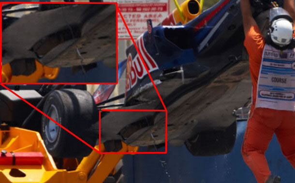
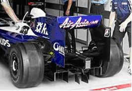
Toyota’s diffuser made a very interesting interpretation of the revised 2009 rules (one that prompted speculation regarding its legality). By exploiting regulations that allowed extra bodywork within a 150 mm zone in the centre of the car, the team appeared to have cleverly shaped the TF109’s rear crash structure (upper red arrow) so that it effectively lengthened and heightened the diffuser’s central section, which also featured a very low splitter at its base (lower red arrows). Because of this upper section of diffuser (extra bodywork), this type of construction was named the “double decker” or “double deck diffuser”.
|
|
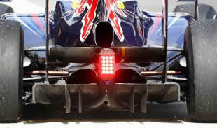
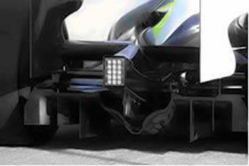
Like engine supplier Toyota, Williams’ interpretation of the revised diffuser regulations was highly innovative. Much of the diffuser’s central section was actually lower than the outer sections. However, clever shaping of the rear crash structure immediately below the rear light effectively created a second central section (see upper arrow). In combination, the result was a central section that exceeded the 175 mm height allowance that applied to the diffuser alone.
BrawnGP version of diffuser
The diffusers of Brawn GP, Toyota, and Williams caused a major stir during the opening two races of the season in Australia and Malaysia, and Ferrari, Renault, Red Bull, and BMW decided to challenge the trio at the ICA (International Court of Appeal). Brawn GP won the first two races with Jenson Button as winner and Rubens Barrichello in second.
The FIA International Court of Appeal (ICA) rejected the protests against the diffusers used by the Brawn, Toyota, and Williams teams, after concluding that their “double decker” designs complied with the 2009 regulations.
BMW Sauber, Ferrari, Red Bull, and Renault had all questioned the legality of the diffusers, but following the hearing on 14 April 2009 in Paris, the ICA decided that race stewards in Australia and Malaysia had made the right call in declaring them legal.
Full statement from the FIA:
The FIA International Court of Appeal has decided to deny the appeals submitted against decisions numbered 16 to 24 taken by the Panel of the Stewards on 26 March at the 2009 Grand Prix of Australia and counting towards the 2009 FIA Formula One World Championship.
Based on the arguments heard and evidence before it, the Court has concluded that the Stewards were correct to find that the cars in question comply with the applicable regulations.
2010: Diffuser Development Continues
After a year of development, 2010 diffusers turned out to be enormously powerful devices with huge downforce values. Red Bull Racing (2010 constructors’ champions) with their 2010 racer ran a double diffuser combined with exhaust gas blowing inside and over it. Throughout 2010, they were almost unbeatable.
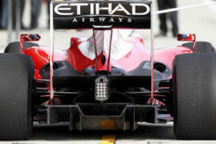
Diffuser on Ferrari F10 during 2010
Diffuser on Mercedes GPW01 - 2010