Chassis Explained
Chassis Design Fundamentals
When designing a racing car, it is important to understand the requirements of the engineering work involved. The nature of the race car’s normal operation and fatigue life depend on the structure and material composition of the car. Therefore, topics such as metallurgy and structural design are important for the designer to grasp.
Any good chassis must achieve several things:
- Be structurally sound in every way over the expected life of the car and beyond. This means that nothing will break under normal conditions.
- Maintain the suspension mounting locations so that handling is safe and consistent under high cornering and bump loads. This means there is no flexing of the body, or at least that flexing is reduced to the lowest possible value.
- Support the body panels and other components so that everything feels solid and has a reliable life span.
- Protect the driver from external intrusion.
Structural stiffness is the basis of what the driver feels through the seat. It defines how a car handles, its body integrity, and its overall feel. Chassis stiffness is what separates a great car to drive from one that is merely acceptable.
Contrary to some explanations, there is no such thing as a chassis that doesn’t flex, but some are much stiffer than others. Even highly sophisticated Formula 1 chassis (actually, Formula 1 has monocoque structure) flex, and sometimes some limited and controlled flexing is built into the car.
The range of chassis stiffness has varied greatly over the years. Basic chassis designs each have their own strengths and weaknesses. Every chassis is a compromise between weight, component size, complexity, vehicle intent, and ultimately cost. Even within a basic design method, strength and stiffness can vary significantly depending on the details.
There is no such thing as the ultimate method of construction for every car, because each car presents a different set of problems.
Some believe an aluminium chassis is the path to the lightest design, but this is not necessarily true. Aluminium is more flexible than steel. In fact, the ratio of stiffness to weight is almost identical to steel, so an aluminium chassis must weigh the same as a steel one to achieve the same stiffness. Aluminium has an advantage only where there are very thin sections where buckling is possible, but that is not generally the case with tubing – only with very thin sheet. Even then, aircraft use honeycombed aluminium to prevent buckling. In addition, an aircraft’s limitation is not stiffness but resistance to failure. Aluminium’s problems are partly overcome by the Audi Aluminium Spaceframe (ASF), which is very expensive and currently limited to a small number of models. More on that later in this article.
Let’s see some chassis basic construction methods from the past and from today. I will explain a bit more two designs employed more in racing: Spaceframe and Monocoque (in a different article about monocoque in Formula 1).
Ladder Chassis (Body on Frame Technology)
This is the earliest kind of chassis. From the earliest cars until the early 1960s, nearly all cars in the world used it as standard. Even today, most SUVs still employ it. Its construction, as indicated by its name, looks like a ladder: two longitudinal rails interconnected by several lateral and cross braces. The longitudinal members are the main stress members. They deal with the load and also the longitudinal forces caused by acceleration and braking. The lateral and cross members provide resistance to lateral forces and further increase torsional rigidity. Since it is essentially a two-dimensional structure, torsional rigidity is very much lower than other chassis types, especially when dealing with vertical loads or bumps.
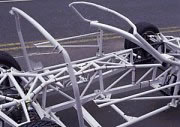
This technology can be found today in some basic auto racing categories. The most well-known is karting. The picture below shows the chassis of a Superkart car without bodywork.
|
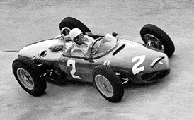
Ferrari’s first car, the “Ferrari 500” (picture left) which carried Alberto Ascari to the marque’s first Formula 1 drivers’ title in 1952, and which become the key car in Ferrari’s journey to becoming the most successful constructor in F1 world championship history, taking the first of the team’s combined total of 31 drivers’ and constructors’ titles, |
Chassis in Superkart with ladder technology not used in racing cars for 60 years, except in kart class of racing. | |
| 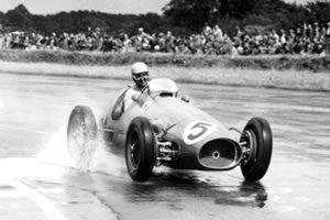 |
was of this type of construction. There was nothing particularly big or clever about the Ferrari 500. It was simply a reworked version of the Scuderia’s previous F2 car: a ladder chassis with transverse leaf springs up front and a De Dion axle at the rear, now located by trailing arms, but with a simpler and much more effective V12 engine. This architecture would remain a mainstay of the Ferrari range for years to come, but in two-litre form it had been well beaten in F2. The Ferrari 500 won every world championship grand prix from May 1952, until Maserati racer Juan Manuel Fangio broke its run at Monza on September 13, 1953. Officially, the “500” competed in 18 races, with 14 wins (77.78%).
Backbone Chassis
|
Lotus Elan Backbone chassis rectangular in cross section |
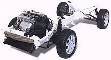
The backbone chassis is a type of car construction that is similar to the ladder design. Instead of a two-dimensional ladder-type structure, it consists of a strong tubular backbone (usually, but not always, rectangular in cross section) that connects the front and rear suspension attachment areas. The tunnel or backbone becomes the primary load-bearing member.
The backbone chassis is very simple: a strong tubular backbone connects the front and rear axles and provides nearly all the mechanical strength.
|
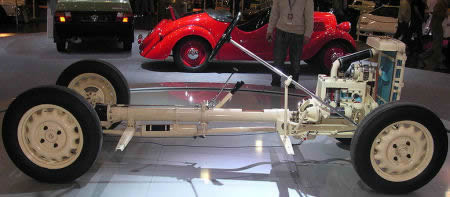
Skoda Rahmen with tubular backbone |
Inside the backbone is space for the drive shaft in the case of a front-engine, rear-wheel drive layout, as in the Lotus Elan. The entire drivetrain, engine, and suspensions are connected to both ends of the backbone. A body is then placed on this structure.
It is almost a trademark design feature of Czechoslovak Tatra heavy trucks (cross-country, military, etc.), but this type of chassis is also often found on small sports cars. It does not provide protection against side collisions, and must be combined with a body that compensates for this shortcoming.
Spaceframe
Spaceframe Chassis
The two most important goals in the design of a race car chassis are that it be lightweight and rigid. Lightweight construction is important to achieve the greatest acceleration for a given engine power. Rigidity is important to maintain precise control over the suspension geometry – that is, to keep the wheels firmly in contact with the race course surface. Unfortunately, these two goals are often in direct conflict. Finding the best compromise between weight and rigidity is part of the art and science of race car engineering.
As the ladder chassis was not strong enough and provided low rigidity values, motor racing engineers developed a three-dimensional design: the tubular spaceframe.
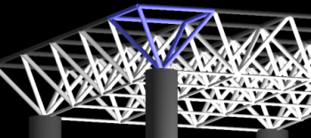
The spaceframe chassis is about as old as the motorsport scene itself. Its construction consists of steel or aluminium tubes placed in a triangulated format to support the loads from suspension, engine, driver, and aerodynamics. A true spaceframe has small tubes that are only in tension or compression, with no bending or twisting loads in those tubes. That means each load-bearing point must be supported in three dimensions.
Tubular spaceframe chassis employ dozens of circular-section tubes (some may use square-section tubes for easier connection to body panels, though circular section provides the maximum strength), positioned in different directions to provide mechanical strength against forces from any direction. These tubes are welded together and form a very complex structure, as shown in the picture.
For the higher strength required by high-performance sports cars, tubular spaceframe chassis usually incorporate a strong structure under both doors, resulting in an unusually high door sill and difficult access to the cabin.
In the early 1950s, Mercedes-Benz created the racing car 300SLR using a tubular spaceframe. This also brought the world the first tubular spaceframe road car, the famous 300SL Gullwing. Since the door sill dramatically reduced cabin accessibility, Mercedes had to extend the doors to the roof, thus creating the iconic “Gullwing” design.
Since the mid-1960s, many high-end sports cars have also adopted tubular spaceframes to enhance the rigidity-to-weight ratio. However, many of them actually used spaceframes for the front and rear structures and made the cabin out of monocoque to cut costs.
There are also inherent advantages to using spaceframes at the amateur level of motorsport. Spaceframes, unlike the monocoque chassis used in modern Formula 1 or CART, are easily repaired and inspected for damage.
Triangulation and Torsional Rigidity
How does triangulation work? The diagram below shows a box with a top, bottom, and two sides, but missing the front and back. When pushed, the box collapses easily because there is no support in the front or back.
Race cars (and any other car, for that matter) need to be supported in order to operate properly, and so the box is triangulated by bracing it diagonally. This effectively adds the front and back which were missing, only instead of using panels, tubes form the brace. See below:
The triangulated box above imparts strength by stressing the green diagonal in tension. Tension is the force trying to pull at both ends of the diagonal. Another force is called compression. Compression tries to push at both ends of the diagonal (shown above in the horizontal yellow tube). In a given size and diameter tube or diagonal, compression will always cause the tube to buckle long before the same force would cause the tube to pull apart in tension.
Spaceframes are fundamentally about tubes held together in compression and tension using 3D pyramid-style structures and diagonally braced tube boxes. A true spaceframe is capable of holding its shape even if the joints between the tubes were hinges. In practice, a true spaceframe is not fully practical, and so many designers use stronger materials to support the open portions of the structure, such as the cockpit opening.
Torsional rigidity applies to spaceframes as well, but because a spaceframe is not made from continuous sheet metal or composite panels as in monocoque design, the structure is used to approximate the same result as the difficulty-to-twist “cigar car” shape (described below).
Another reason torsional rigidity is so important is that it greatly affects suspension performance. The suspension itself is designed to allow the wheels/tires to follow the road’s bumps and dips. If the chassis twists when a tire hits a bump, it acts like part of the suspension, meaning that tuning the suspension becomes difficult or impossible. Ideally, the chassis should be ultra-rigid and the suspension compliant.
|
|
It is important to ensure that the entire chassis supports the loads expected and does so with very little flex.
The advantage of a spaceframe is that it is very strong in any direction compared with a ladder chassis and a metal monocoque chassis of the same weight. The disadvantage is that it is very complex, costly, and time-consuming to build. It is impossible to produce using robotised production. Besides, it engages a lot of space, raises the door sill, and results in difficult access to the cabin.
Ferrari 156 Sharknose spaceframe
The Ferrari 156 “Sharknose” was the first Ferrari Formula 1 car to win the constructors’ championship and the first competitive Ferrari F1 car with a rear-mounted engine. It also carried Phil Hill to the 1961 title after the death of team-mate Wolfgang von Trips in the Italian Grand Prix at Monza.
Over the winter of 1959, Ferrari’s engineers, led by Carlo Chiti, laboured in secret. As F1 downsized to 1.5 litres, British teams were caught off guard, but Enzo had a car and engine ready to go. Chiti’s 156 was a wishbone-suspended tube-frame chassis (pictures), evolved from the 246P but slimmer in profile. This made it better able to minimise air resistance with less power pushing the car. To maximise that advantage and reduce the centre of gravity, Chiti flattened the “vee” from 65 degrees to 120 degrees. The radiators were fed by distinctive nostril air intakes. With up to 40 bhp more than their competitors, it was almost all-conquering in 1961, except for Stirling Moss’s genius at Monaco and the Nurburgring.
Audi Aluminium Space Frame (ASF)
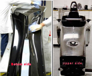
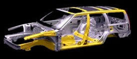
Audi A8 Spaceframe in FEA |
|
| Audi A8 was the first mass production car featuring Aluminium Space Frame (ASF) chassis. Developed in conjunction with US aluminium maker Alcoa. ASF is intended to replace conventional steel monocoque mainly for the benefit of lightness. |

Audi claimed the A8’s ASF was 40% lighter yet 40% stiffer than a contemporary steel monocoque. This enabled the 4WD-equipped A8 to be lighter than the BMW 740i.
ASF consists of extruded aluminium sections, vacuum die-cast components, and aluminium sheets of different thicknesses, all made of high-strength aluminium alloy. At the highly stressed corners and joints, extruded sections are connected by complex aluminium die castings (nodes). New fastening methods were also developed to join the body parts together. The construction is quite complex, and production cost is far higher than steel monocoque.
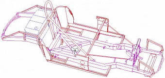
|
|
Audi A2 and its spaceframe in CAD |
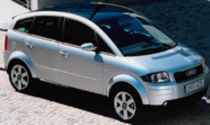
The Audi A2 employed the second generation of ASF technology, which involved larger but fewer frames, hence fewer nodes and requiring less welding. Laser welding was also extensively used in the bonding. All of this helped reduce production costs to the extent that the affordable A2 could benefit from the technology.
The advantage of this construction is that it is lighter than steel monocoque and equally space-efficient.
|
|
Audi R8 high class sport car | |
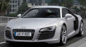
Audi employed the same technology in 2009 for the Audi R8 high-performance sports car. The production methods are more elaborated and technically more efficient, but the process is still too expensive for mass production.
Monocoque
Monocoque Chassis
In contrast to spaceframes, the monocoque chassis uses panels, just like the sides of the box pictured above. Instead of small tubes forming the shape of a box, an entire panel provides the strength for a given side.
A common shape for 1960s racing cars of monocoque construction was the “cigar”. The cylindrical shape helped impart torsional rigidity – the amount of twist in the chassis accompanying suspension movement. See the diagram below.
Monocoque, from the Greek for single (mono) and the French for shell (coque), is a construction technique that supports structural load by using an object’s external skin as opposed to an internal frame covered with a non-load-bearing skin. Monocoque construction was first widely used in aircraft in the 1930s. “Structural skin” or “stressed skin” are other terms for the same concept. A welded unit body is the predominant automobile construction technology today.
Today, 99% of cars produced worldwide are made of steel monocoque chassis, thanks to low production cost and suitability for robotised production.
A monocoque is a one-piece structure that defines the overall shape of the car. In fact, the “one-piece” chassis is actually made by welding several pieces together. The floorpan, which is the largest piece, and other pieces are press-made by large stamping machines. They are spot-welded together by robot arms (some even use laser welding) on a stream production line. The whole process takes just minutes. After that, accessories such as doors, bonnet, boot lid, side panels, and roof are added.
Monocoque chassis also benefit crash protection. Because the construction uses a lot of metal, crumple zones can be built into the structure. Another advantage is space efficiency. The whole structure is essentially an outer shell; unlike other kinds of chassis, there is no large transmission tunnel, high door sills, or large roll-over bar. This is very attractive for mass-production cars.
There are many disadvantages as well. Monocoque construction is very heavy, owing to the amount of metal used. As the shell is shaped to benefit space efficiency rather than strength, and the pressed sheet metal is not as strong as metal tubes in spaceframe construction or extruded metal, the rigidity-to-weight ratio is the lowest among all kinds of chassis except the ancient ladder or backbone types.
Although monocoque is suitable for mass production by robots, it is nearly impossible for small-scale production. The setup cost for the tooling is too expensive, requiring large stamping machines and expensive moulds.
Carbon-Fibre Monocoque
Carbon-Fibre Monocoque
Carbon fibre is the most sophisticated material used in aircraft, spacecraft, and racing cars because of its superior rigidity-to-weight ratio and very high cost.
In the early 1980s, the FIA established the Group B racing category, which allowed the use of virtually any technology available as long as a minimum of 200 road cars were produced. As a result, road cars featuring carbon-fibre body panels started to appear, such as the Ferrari 288GTO and Porsche 959.
Production Process
Carbon-fibre panels are made by laying carbon-fibre sheets (a material similar in appearance to textile) on either side of an aluminium or Kevlar paper honeycomb insert. The honeycomb, which defines the shape of the panel, is bonded with several layers of carbon-fibre sheets impregnated with resin, then cured in a large oven at 120 degrees Celsius and 6 bar (90 psi) pressure. After curing, the carbon fibre composite melts and forms a uniform, rigid body panel.
The use of composite materials in monocoque skins now allows strength, stiffness, and flexibility to be controlled in different fibre directions. Careful design of the direction of the fibres in successive layers of materials used in the skin can produce different mechanical properties in different directions while optimising for weight. Composite materials can be readily built up into complex three-dimensional shapes, making them ideal for many components. They can also be built to be flexible only in useful ways.
There are several fibre types commonly used in the motor industry. Kevlar, developed by Du Pont, offers the highest rigidity-to-weight ratio among them. Kevlar can also be found in the body panels of many exotic cars as anti-intrusion protection. Carbon fibre is used in even larger quantities. Glass fibre is found in less expensive but still strong parts. Aluminium honeycomb panels are often used for monocoque construction as part of a composite structure or as a loaded part by themselves.
The large number and types of functional demands on the monocoque, coupled with the multiple plies needed for the carbon or any other composite laminate, create a complex loading situation that requires detailed static and dynamic analysis capabilities. Engineering teams use sophisticated software to optimise the design of the monocoque chassis and engine frames. Finite element analysis (FEA) programs, used by many automotive companies for their ability to model multiple materials and to simulate short-duration impact dynamics and complex contact conditions among multiple components, are employed. The software can help determine optimum locations for attachment points and orientation of the fibres.
Use of a carbon/epoxy monocoque is, therefore, a huge advantage in terms of parts integration, giving design freedom to customise the laminate at the attachment points to avoid undue stresses or delamination.
Carbon-Fibre Panels vs Carbon-Fibre Monocoque Chassis
The Porsche 959, which employed carbon fibre in body panels only, is obviously inferior to the McLaren F1’s carbon-fibre monocoque. The McLaren’s structure not only supports the engine, drivetrain, and suspensions, but also serves as a very rigid survival cell.
Exotic car makers often claim their cars employ carbon fibre in construction. This sounds very advanced, but the important question is: where is the carbon fibre used – in body panels or the chassis?
Most so-called “supercars” use carbon fibre in body panels only, such as the Porsche 959, Ferrari 288GTO, Ferrari F40, and even the Porsche 911 GT1. Since body panels do almost nothing to provide mechanical strength, the use of carbon fibre over aluminium can barely save weight. The stress member remains the chassis, which is usually a heavier and weaker steel tubular frame.
|
Carbon fiber monocoque chassis of McLaren F1 sport car |
Truly sophisticated is the carbon-fibre monocoque chassis, which had at the time only appeared in the McLaren F1, Bugatti EB110SS (not the EB110GT), and Ferrari F50. It provides superior rigidity while optimising weight. No other chassis construction can match it.
The carbon fibre monocoque made its debut in Formula 1 in 1981 with McLaren’s MP4/1 racing car, designed by John Barnard. It is no surprise that the McLaren F1 was the first road car to feature this technology.
Unlike the McLaren F1, the Ferrari F50’s rear suspensions are directly bonded to the engine/gearbox assembly, the same arrangement as in a modern Formula 1 car. This means the engine becomes the stressed member supporting the load from the rear axle. The entire engine/gearbox/rear suspension structure is then bonded into the carbon-fibre chassis through light alloy. This was a first for a road car.