Rapid Prototyping (RP), Rapid Manufacturing (RM), and 3D Printing
|
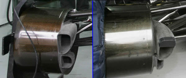
Sauber (Australia GP 2011) like many other teams runs non carbon brake ducts which are manufactured via Rapid manufacturing method. This method can produce components faster with reduced manufacturing time up to 90%, and cheaper. RM and RP can achieve extreme structural accuracy and be able to create almost any shape . |
Overview
Many Formula 1 teams use non-carbon brake ducts, sections of the floor, air ducts, and many other parts that are manufactured via rapid prototyping methods. Strictly speaking, this type of manufacturing is called rapid manufacturing (RM), although the process is the same – only the materials differ.
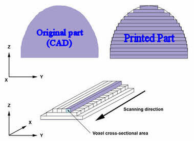
Rapid prototyping or manufacturing decreases development time by allowing corrections to a product to be made early in the process. Mistakes can be corrected and changes can be made while they are still inexpensive. RP or RM can achieve extreme structural accuracy and produce almost any shape. The parts are first designed in a CAD (Computer Aided Design) system and then, with the help of 3D laser printing technology, are manufactured layer by layer from material in powder form until the model is complete.
Rapid Prototyping (RP) or Rapid Manufacturing (RM) can be defined as a group of techniques used to quickly fabricate a scale model, usable part, or assembly using three-dimensional CAD data. What is commonly considered the first RP technique, stereolithography, was developed by 3D Systems of Valencia, California, USA. The company was founded in 1986, and since then a number of different RP techniques have become available.
The Five-Step Process
Although several rapid prototyping techniques exist, all employ the same basic five-step process:
- Create a CAD model of the desired part
The object is built using a Computer-Aided Design (CAD) software package. The designer can use a pre-existing CAD file or create one specifically for prototyping purposes. This step is identical for all RP or RM building techniques.
- Convert the CAD model to .stl (stereolithography) format
The various CAD packages use different algorithms to represent solid objects. To establish consistency, the .stl format has been adopted as the standard of the rapid prototyping industry. Since the .stl format is universal, this step is identical for all RP build techniques.
- Slice the .stl file into thin cross-sectional layers
A pre-processing program prepares the .stl file for building. Several programs are available, and most allow the user to adjust the size, location, and orientation of the model. Build orientation is important for several reasons. First, properties of rapid prototypes vary from one coordinate direction to another – prototypes are usually weaker and less accurate in the z (vertical) direction than in the x-y plane. In addition, part orientation partially determines the time required to build the model. The pre-processing software slices the .stl model into layers from 0.01 mm to 0.7 mm thick, depending on the build material. Each RP machine manufacturer supplies its own proprietary pre-processing software.
- Construct the model one layer atop another
The actual construction of the part takes place in this step. Using one of several techniques, RP machines build one layer at a time from WINDFORM carbon-fibre-filled materials, polymers, plastic, paper, ceramic, or powdered metal. Most machines are fairly autonomous, requiring little human intervention.
- Clean and finish the model
The final step involves removing the prototype from the machine and detaching any supports. Some photosensitive materials need to be fully cured before use. Manufactured parts may also require minor cleaning and surface treatment. Sanding, sealing, and painting the model will improve its appearance and durability.
From Prototyping to Manufacturing
|
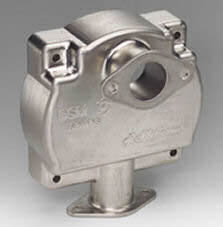
Metal part produced using RM method with metal 3D printing |
A natural extension of RP is rapid manufacturing (RM): the automated production of parts directly from CAD data. Currently only a few final products are produced by RP machines, but the number will increase as metals and other materials become more widely available and less expensive. RM will never completely replace other manufacturing techniques, especially in large production runs where mass production is more economical.
For short production runs, however, RM is much cheaper since it does not require tooling. RM is also ideal for producing custom parts tailored to exact specifications. The other major use of RM is for products that simply cannot be made by subtractive (machining, grinding) or compressive (forging) processes. This includes objects with complex features, internal voids, and layered structures.
Application in Motorsport
|
The Audi RSQ, car from “I-robot” movie was made by Audi with rapid prototyping industrial KUKA robots |
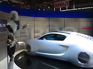
In the world of motorsport, time is everything. With competitive stakes so high, every team wants to be ahead when it comes to designing, wind tunnel testing, and race track testing of their car. Even in Formula 1, budgets have limits. The sooner a model is built, the sooner it can be tested on track. That is why rapid prototyping and rapid manufacturing are so important.
Aerodynamic testing in wind tunnels is a major element in the manufacturing procedure, and it can only proceed after a successful rapid prototype of the final assembly has been produced.
Rapid prototyping and manufacturing in motorsport involve the use of solid freeform fabrication techniques to create a physical model of the car (scaled or full size), beginning with a blueprint of the final aerodynamic design. This design is taken from the drawing board to the computer.
Aston Martin LMP1 Case Study
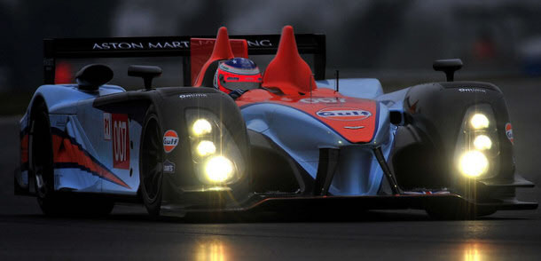
The Aston Martin LMP1 prototype car designed for 2011 competition was entirely prototyped with the help of RP. George Howard Chappell and his team developed a car from scratch in just six months. One tool they employed was a pre-release version of PTC’s Creo; another was highly advanced 3D printing. The Stratasys Dimension printer was used to mock up the chassis, driver controls, and engine of the race car. The 3D printer also produced prototypes for concept and aero testing of Aston Martin’s new chassis. Aston Martin Racing explored the idea of using the 3D printer to make finished parts to bolt onto the car, including the front wing splitters used for aerodynamic flow.
|
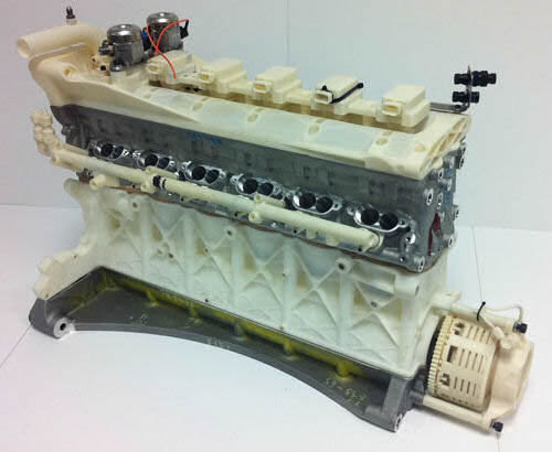
| > ###### AMR team selected the Dimension machine for its rapid prototyping capabilities after seeing the speed and quality of the parts produced for the Prodrive run rally team in a previous project. Having the machine on site helped the race team to design, test and build a complete car to meet the tight deadline for entry into this (2011) year's ILMC. The Dimension machine was used primarily for designing and testing the engine mock up (picture above), engine parts as well as mocking up the chassis and driver controls. |
Materials: WINDFORM and Carbon-Filled Compounds
Manufacturers are using advanced technology to bring about significant improvements in the overall quality of rapid prototyping and manufacturing products. Commercially used materials for the rapid manufacturing of motorsport components include carbon-filled WINDFORM material, used by almost every Formula 1 team. The aim is to test as many iterations of desired parts as possible at the lowest possible cost. Previously, team model shops physically made parts by hand, resulting in long production times and high costs. Today, racing teams including Formula 1 use WINDFORM carbon fibre-filled materials both for wind tunnel models and for the racing cars themselves.
|
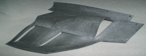
Today RedBull Racing is using a lot WINDFORM carbon filled materials both for wind tunnel model and for the racing car. On the picture, part of the floor. |
Metal 3D Printing: Selective Laser Sintering
The next step required by all F1 teams is direct metal deposition or sintering, which enables the design of parts without traditional manufacturing constraints. This allows teams to make quick design modifications during the season – for example, changing suspension fittings on wheel uprights to improve vehicle dynamic performance, adding ribs to increase stiffness and reliability, or repairing broken parts. The main requirement is direct sintering of composite metals or very high-performance alloys.
There are three familiar methods of working with metal: casting (pouring it into a mould), forging (beating it into shape), and machining (carving from a solid block). A fourth method can now be added to that list: printing – or, more technically, selective laser sintering (SLS).
How SLS Works
The process begins with a fine metal powder – any metal that can be welded, but most often titanium, since it is difficult to machine and costly to process. The powder sits in hoppers, and a single layer around 20 to 30 microns (0.02 to 0.03 mm) thick is spread on a platform by a recoating arm. Using the CAD data, a precision laser then “draws” the shape of the part, melting and welding the first layer before the platform drops by 20 to 30 microns. Another layer of powdered metal is spread out and the laser goes to work again. This process repeats many times over.
The 0.5 mm-wide laser dances and zaps over the powder, throwing sparks into the inert argon gas chamber. The laser itself penetrates beyond a single layer, bonding (welding) the layers to each other. At the end of the process, the welded piece is removed and the excess powder dusted off. Finished parts may also require minor cleaning and surface treatment such as sanding.
|
The use of additive manufacturing for rapid prototyping takes virtual designs from computer aided design (CAD) or animation modeling software, transforms them into thin, virtual, horizontal cross-sections and then creates successive layers until the model is complete. It is a WYSIWYG (What You See Is What You Get) process where the virtual model and the physical model are almost identical. Laser zaps over the powder in determined patern to create final product. |
Capabilities and Limitations
There are limitations: EADS’ largest machine has a chamber measuring 60 centimetres by 60 centimetres deep, which sets the maximum component size. Building something that size would take around two days, but this is still much faster and cheaper than hand-made parts.
The beauty is that the complexity of the manufactured part does not add cost. The metal is worked at a molecular level, and the laser can draw any shape – structures can be left hollow or layered, and unused powder is fed back into the hoppers and reused.
Formula 1 is an ideal application for this technology, as teams use high-value parts in low quantities. It is reported that since Daimler is a major shareholder in EADS, a leader in metal printing technology, several parts of the 2011 Mercedes GP car may have been built using metal RM.
Roll Hoop Demonstration
|
Formula One roll structure made using the SLS process from titanium powder stock |
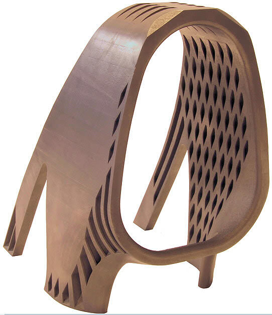
One company closely involved with Formula 1 teams in rapid prototyping and manufacturing went so far as to produce a complete roll hoop to demonstrate the capabilities of its manufacturing process. A roll hoop is a complex component required to fulfil several important tasks. Its primary function is to protect the driver’s head in the cockpit, but it also serves as an air intake, a camera mount, and a pick-up point for lifting the car with a crane.
The roll hoop is one of the highest points on a Formula 1 car, and a traditionally built roll hoop is a heavy component to have positioned so high. Any reduction in weight could be highly beneficial from a vehicle dynamics perspective, so the company set a target weight of 1 kg – a potential saving of 1 to 2 kg over a traditionally manufactured item.
The resulting roll hoop was produced from Ti6-Al-4V titanium alloy, making it both lightweight and strong. It contained internal features that would be exceedingly difficult and costly to produce using other manufacturing methods. The part maintained its aerodynamic profile and featured an area for the addition of a camera mount or other component. Although it had not been subjected to FIA crash tests and was not manufactured for any specific car, it was modelled and subjected to FEA assessment to ensure it would meet the same requirements as a traditionally manufactured part.
Trackside 3D Printing
The latest development in rapid manufacturing in F1 was Red Bull Racing’s decision in 2011 to have two rapid prototyping machines travelling to the races inside the trucks. The machines may use stereolithographic or laser sintering techniques (the difference being that the first uses photopolymer resin and the second uses powders melted together by laser). In both cases, the laser fuses the material while scanning a cross section. The process is repeated with a new layer added with each scan until a finished piece is completed.
These processes are now so advanced that metal parts can be created, although most of the work involves components such as brake ducts. The biggest challenge with these systems is getting the data from computers at the factory, where a part is designed, to the transporter at the circuit. The benefit is that new parts are available on site and do not have to be flown out once the work is done – they can simply be fitted to the car.