Aerodynamic testing of open wheeled racing car
Southampton University 8 January 2004
The text of this article is courtesy of: Willem Toet, Professor of Motorsport Engineering (The University of Bolton), Aerodynamics Advisor, former F1 Head of Aerodynamics at Sauber, Ferrari, Benetton, BAR Honda
**ABSTRACT **
This note outlines what will be presented in the lecture. The main topic is the Aerodynamic testing of Formula racing cars and how this testing is done. Subjects included include the process of getting a model into a wind tunnel from concept and detailed design through manufacturing to testing and analysis of the data produced. Some discussion of the compromises between different performance parameters is included.
A short discussion of the history of aerodynamic testing for race-cars and the improvements made in conceptual testing included with reference to the most efficient was of spending different sizes of budget.
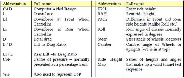
NOMENCLATURE
**1. INTRODUCTION **
The idea of this paper is to add to the very limited material available on how aerodynamic testing is done for formula race cars. A great deal of equivalent aircraft material exists despite the equally secretive nature of that business possibly because it has been done for so much longer. In many ways the aerodynamics of race cars is simpler than aircraft testing in that roll roll and pitch angle changes are tiny but the presence of ground effect mean that pitch variation can cause large force changes despite this and moving ground planes add a dimension of complexity and interest. Recent developments in road simulations have allowed for the use of pneumatic tyres which offers the prospect of reducing one of the largest errors in recent race car simulation.
2. THE RULE BOOK
The rulebooks for Formula cars are often complex and confusing. Like most present generation of race-car regulations the Formula-One rulebook (3) has been specifically written to limit the amount of downforce the cars produce, thus restricting maximum speeds to a ‘safe’ level. It provides tight limitations on the aerodynamic surfaces of the racing car and includes extensive exclusion zones for “aerodynamic” devices.
In the rules for the year 2000 the front-wing profile must fit into a box that limits its maximum and minimum heights, and fore and aft positions. The rear wing is similarly limited, but with the addition that in front elevation the upper portion may only fill 70% of a defined legality box. Over most of the underside the car must have a flat continuous floor, but at the trailing edge the floor is allowed to curve up to form a diffuser. These are only a selection of some of the rules, spread over more than 40 pages, that apply to year-2000 F1 cars.
As aerodynamicists refine cars designed to a particular set of rules, downforce levels increase, and hence so do cornering speeds, until it is felt necessary to modify or rewerite the rule book. This presents aerodynamicists with a moving target – as the rules change, so do acceptable downforce, drag and efficiency levels. Because of this, the comments presented here are only true of Formula One cars designed to the year-2000 rulebook – although some comments remain valid for many forms of performance-car aerodynamics.
**3. THE CIRCUITS **
A Formula-One race track combines a series of straights and corners. In the corners, aerodynamic downforce is needed to increase tyre grip, and hence cornering speed. In contrast, it is drag that limits top speed. High downforce is achieved by increasing the angles of the various wing elements, and adding additional aerodynamic surfaces. Increasing downforce therefore increases the trailing-vortex drag and the zero-downforce drag, so there is an unavoidable compromise between downforce and drag. A circuit with a preponderance of slow corners and short straights (e.g. Monaco) will have this compromise biased towards downforce, whilst a circuit with a large number of long straights (e.g. Hockenheim) will be biased towards lower drag. These circuits are loosely referred to as ‘high-’ and ’low-downforce’, respectively.
**4. SOME TERMS **
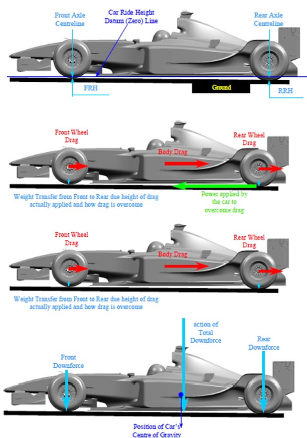
In side elevation the attitude of an aircraft is defined through angle-of-attack and / or pitch. The relevant terms for a racing car are the ride heights – the distance of specific datum points from the ground plane. Figure 1 Illustrates typical ride-height definitions for a year-2000 Formula-One car. In this example the front-ride height (FRH), and rear-ride height (RRH), are measured at the front and rear axle lines, from a z=0 datum that corresponds to the bottom of the flat floor specified by the rulebook. (This is not the plane closest to the ground as the rules mandate a skid block is mounted directly below the floor). In Figure 1 the car is pitched rear up, so the z=0 datum is not parallel to the ground plane, and the value of FRH in Figure 1 is close to zero. The precise definition of ride heights will vary from team to team.
Typical extremes of front ride height for a year-2000 car are between 0 and 40mm, whilst the corresponding values for the rear are between 10 and 70mm. The difference between the rear and front ride heights give the pitch of the car, which is often expressed as a distance rather than an angle, or sometime as Rake angle. The term ‘ride-height map’ is used to describe a collection of front- and rear-ride height combinations.
In addition to generating downforce and drag, the car also generates a pitching moment. For convenience, this system is usually broken down into a drag component that acts through the ground plane, a front downforce that acts through the front axle line, and a rear downforce that acts through the rear axle line. The balance point for this force system is the centre of pressure (CoP). For simplicity, in Figure 1 only the effect of the downforce components on CoP is included, but drag forces will also alter its location.
The CoP is usually measured forward from the rear-axle line, and expressed as a percentage of wheelbase. Typical values for a year-2000 F1 car are between 34% and 44%.
5. THE OBJECTIVES
Formula-One aerodynamicists have two principal duties – improving the racecar, and providing aerodynamic data for those who need it.
The first task occupies the bulk of the aerodynamicists’ time. This involves the analysis of existing data, design of new parts, and testing them. Whether a new part is considered an aerodynamic improvement depends on a number of factors. Usually a target drag level and CoP will have been specified, based on the circuit, and the aerodynamicist will try to maximise the lift-to-drag ratio. At the same time, any modification must not degrade the cooling or pitch sensitivity of the racecar.
Disseminating aerodynamic data is no less important – there is no point in developing a racing car with excellent aerodynamics if those running the cars do not know how best to exploit this potential. Once a configuration is ‘frozen’, and issued for manufacture, it is tested exhaustively for a range of front and rear wing settings, and for whatever bodywork options are available. This aerodynamic data is used by the race engineers to asses, for example, which wing settings and cooling options should be used at a particular race meeting.
This data is also passed onto the engineers responsible for computational simulations of track performance. They will use these simulations before a race, for example to fine-tune the mechanical and aerodynamic setups, or to evaluate different pit stop strategies during the race.
Gathering this aerodynamic data is referred to as ‘mapping’, and the resultant document that describes the aerodynamic characteristics is the ‘aero map’ or ‘aero manual’ for the car.
6. WIND-TUNNEL TESTING
Although Computational Fluid Dynamics, such as panel methods or Navier-Stokes codes, will have been used to design some parts of a year-2000 Formula-One Car, the car will have been developed predominately in the wind tunnel. Typically a 40%- or 50%-scale model will have been used, at tunnel speeds of 30 to 60mi/h, so Reynolds numbers are still below full-scale values. For example, a 0.5m chord rear wing on the full-size car at 200km/h has a Reynolds number of 1.9 million, wheras a 50% model of this rear wing at 50m/s will have a Reynolds number of 0.85 million.
Most wind tunnels in use in this era are closed-circuit, and all have moving ground planes. Fully enclosed, adaptive-wall, slotted-wall, and open-jet tunnels all have their proponents. The advantages and disadvantages of these different designs are outlined in general terms by Barlow, Rae & Pope (4), and, in more specific terms with respect to motor-racing applications, by Knowles & Finnes (5).
The attitude and height of the model above the moving-ground is controllable. The ride-height map used in the tunnel will typically comprise of 10 to 20 different FRH / RRH combinations, and be intended to simulate the behaviour of the car through typical acceleration and braking manouvers, and through the speed range. Some wind tunnels also allow the effects of yawing the road and model to be investigated, and for the front wheels to be angled relative to the car centreline, to simulate the effect of steering lock.
Forces acting on the wind-tunnel model are measured using a six-component balance, either overhead, or within the model, with additional balances used to separate out the loads on the wings. The wheels can be attached in one of two ways:
1. Wheels-on: Just like the full-size car, the wheels are attached to the model using suspension arms, and the wheel forces are included as part of the whole-car values measured on the balance
2. Wheels-off: Separate mounting arms that extend outboard of the wheels are used, and each arm has a separate load cell to measure wheel drag. Changing the ride-height of the car alters the positions of the suspension pick-up points relative to the wheels, so on a wheels-off system it is necessary to motorise the suspension system so that it moves as if the outboard end (the ‘upright’) were in fact connected to the wheels.
The wheels-off system is more complicated than the wheels-on version, but does allow separate wheel forces to be extracted, and typically gives more repeatable results.
7. MODEL DESIGN
The wind-tunnel model is designed using 3-D Computer Aided Design (CAD). This allows large numbers of subtly differing components to be designed rapidly; enables data to be transferred directly to manufacturing; and for geometry to be quickly transformed into full-scale parts.
The model is usually built up around a central spine (aluminium or carbon fibre) around which the external bodywork will be built up. The bodywork is split into a number of components, designed to allow alternative parts to be evaluated. These components are usually made from carbon fibre, as this gives a good surface finish, is light and stiff, yet easily trimmed so small modifications can be evaluated. Wing elements are often machined direct from solid aluminium, to give the desired accuracy of profile and rigidity under aerodynamic loading, whilst some components are produced using rapid prototyping methods.
8. DOWNFORCE / DRAG LEVELS
The lift-to-drag ratio of a racing car varies with the downforce level. At the higher downforce levels the lift-to-drag ratio is at its lowest, and it is difficult to gain more downforce efficiently. As the downforce is reduced, the lift-to-drag ratio improves, but reaches a maximum at a low-to-medium downforce level. Achieving the optimum lift-to-drag ratio for a given drag or downforce level may simply be a matter of changing wing elements, but can involve fitting different body parts.
Averaged across the ride-height map, a year-2000 Formula-One car in high-downforce setting will generate at least 8,000N of downforce at 200km/h. Generally about one-third of the total downforce acts on the front wing, and one-third on the rear wing, but this split will vary with downforce level, and between different designs.
The average lift-to-drag ratio of the whole car is of the order of three-to-one. Just as an aircraft aerodynamicist may talk about ‘drag counts’, a Formula One aerodynamicist may talk about ‘points’ of efficiency, where a one-point gain in lift-to-drag ratio corresponds to an increase of 0.01 in the liftto- drag ratio. A typical improvement in the lift-to-drag ratio between the start of one season and the next for a year-2000 F1 car is of the order of 5% (e.g. a 15 point increase from 3.00 to 3.15). As many teams tunnel-test full-time throughout the year, this gain will have been earned through about 3,000 to 4,000 hours of tunnel testing.
9. FRONT-FLAP-TYPE CHANGES
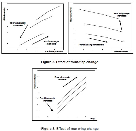
The front flap is used to achieve the desired centre of pressure, often referred to as ‘balancing’ or ’trimming’ the car. Increasing the angle of the front flap increases front downforce, but the total downforce is increased by a smaller amount, because downforce is lost from the rear of the car, as illustrated in the right half of Figure 2. Sometimes there is a small trade-off between front wheel and body drags, but the total drag remains relatively constant. Increasing the front flap angle therefore pushes the centre of pressure forward, and improves the overall lift-to-drag ratio, as illustrated in the left half of Figure 2. The strength of this flap change usually increases as the downforce level is reduced, and it also varies with detail design. For a year-2000 F1 car, increasing the front flap by one degree will typically shift the average CoP forward by 1%, improving the lift-to-drag ratio by between 0 and 3 points.
There are some limits that prevent this gain in lift-to-drag ratio being fully exploited. The first is that the maximum flap angle is limited by rules that dictate a maximum height. In addition, increasing the front-flap angle can introduce localised flow separations, in which case the efficiency is increased only weakly, or is reduced. Finally, pushing the centre of pressure too far forward may introduce unfavourable driving characteristics.
This change in lift-to-drag ratio accompanied by a movement in CoP can be found from a large number of detail changes, not just to the front flap. A modification that increases the aerodynamic efficiency is only judged to be an ‘improvement’ if it does not move the CoP further forward than a flap change giving the same increase in lift-to-drag (assuming that there is no change in pitch sensitivity or cooling).
10.REAR-WING-TYPE CHANGES
Assuming enough front downforce is available to trim the car to the desired CoP, the rear wing controls the total downforce, as well as the total drag. When the rear-wing downforce is increased, an interaction between the rear wing and the underfloor of the car means that the total downforce is increased by a greater amount. The rear wing has a relatively weak effect on the front downforce generated by the body (and even less effect on the front-wing downforce), so increasing the rear-wing downforce shifts the CoP aft. Unlike a front-flap change, increasing the rear-wing downforce also increases the total drag, as illustrated in Figure 3. The compromise between downforce and drag discussed earlier, is therefore really a compromise between rear downforce and drag.
A change which increases the rear downforce is gauged by the ratio of change in rear downforce to change in total drag (Lr / D). The level of this ratio varies from circuit to circuit. At a high downforce circuit, with few straights, a higher drag penalty can be accepted for small changes in rear downforce, and the minimum acceptable value of Lr / D for an efficient rear wing change is low (near unity for a year-2000 F1 racecar). At medium downforce circuits the minimum acceptable Lr / D slope increases, up to values of the order of 1.5.
As was the case for front-wing-type changes, there are modifications to the car other than just altering the rear wing angles that give rear-wing-type changes. With these, the object of the optimisation process is to ensure that any increases in rear downforce are attained at a higher Lr / D ratio than can be achieved by increasing the rear wing angles. As this ratio alters with downforce level, the aerodynamicist must know an acceptable ratio, usually obtained from computer lap simulations, prior to optimistation.
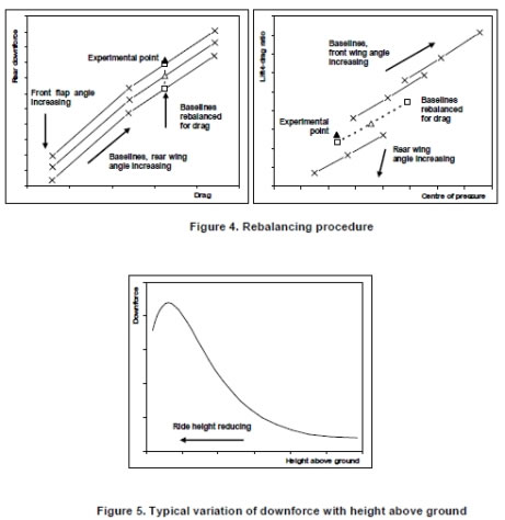
11.REBALANCING
Some modifications alter downforce, CoP and drag in a complex pattern that makes it unclear straight away whether the change is beneficial or not. In such cases, the data is often compared to a ‘rebalanced’ baseline.
This process is illustrated in Figure 4. In the left-hand portion of the figure is a series of curves (solid lines) showing typical baseline rear wing changes (rear downforce vs drag) for different front flap angles. Superimposed is some hypothetical experimental point (solid triangle) that we want to compare to the baseline configuration to see if it is an improvement.
The first stage in the rebalancing process is to perform a notional rear wing change to the baseline data to match the drag level of the experimental point. The rebalanced-for-drag baseline point on the curve for the same front flap angle is indicated on the LHS of Figure 4 as an open triangle. This is linked by a chained line to two rebalanced-for-drag points that corresponding to the higher and lower flap angles (open squares).
Having matched the drag level, the baseline data must then be rebalanced to the same centre of pressure, by performing a notional front flap change. This is illustrated in the RHS of Figure 4, which shows front baseline front-flap changes (lift-to-drag ratio vs CoP) for three different rear wing settings (solid lines); the experimental point (solid triangle); and the front-flap change curve for the baseline data rebalanced to the experimental drag level (chained line with open symbols). The values of downforce and CoP for the rebalanced-for-drag curve are estimated by interpolating between the baseline data, using the notional rear-wing change needed to match the experimental drag level. In the example given in Figure 4, at the same CoP the experimental point has a better lift-to-drag ratio than the rebalanced-for-drag baseline, and therefore represents a beneficial change.
**12.PITCH SENSITIVITY **
The previous comments have concerned forces averaged across the ride-height map, but the effect of some modifications varies with ride height. Such changes are said to affect the ‘pitch sensitivity’, which is the catch-all term used to described how the aerodynamics of a racing-car are influenced by variations in front- and rear-ride heights (and vice-versa). This is particularly important in dynamic situations, such as braking and accelerating.
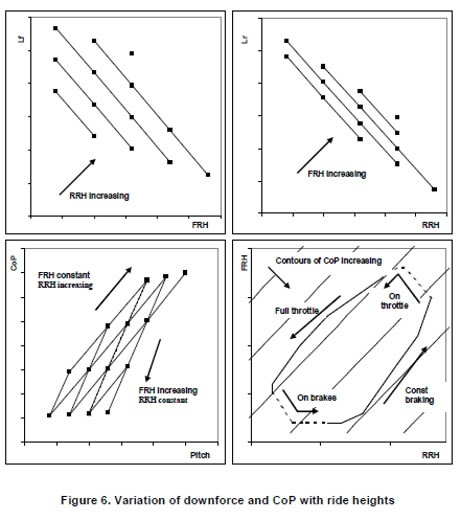
The pitch sensitivity of the racing car is partly affected by the interference between the front wing and the ground plane, and between the underbody (flat floor and diffuser) and the ground plane. The generic behaviour of isolated bodies in ground effect has been well documented (e.g. by Zerihan & Zhang (6) for front wings, and Senior (7) for underbodies). They have shown that both wings and bodies have a similar generic behaviour, which is plotted in Figure 5. At high ride heights there is a weak increase in downforce as the body is brought closer to the ground. At medium ride heights there is a much stronger increase in downforce as the ride height is reduced. At a critical ride height, the body starts to stall, and the slope of the downforce curve rolls off as the ride height reduces. The variations of front and rear downforce with front and rear ride height for a typical year-2000 F1 car are illustrated in, respectively, the top-left and top-right portions of Figure 6. Assuming the front wing does not stall, the front downforce increases as the front ride height is reduced.
In addition to this, there is an interaction between front and rear: if the FRH is kept constant and the RRH increased, there is an increase in front downforce, so the Lf vs FRH plot in the top left of Figure 6 shows a series of parallel curves. As well as increasing front downforce, increasing the RRH at constant FRH results in a reduction in rear downforce, and a forward shift in CoP. If there is no diffuser stall, the rear downforce reduces as the rear ride height increases, as illustrated in the top right of Figure 6.
As with the front, there is a cross-coupling, and at a constant RRH, increasing FRH increases rear downforce, leading to a series of parallel Lr vs RRH curves. Increasing FRH for a constant RRH also reduces front downforce, and shifts the CoP aft. The effect of variations in FRH and RRH on CoP is also illustrated in the carpet plot presented in the lower left corner of Figure 6, which plots centre of pressure against pitch (defined as RRH – FRH), with lines of constant front and rear ride height. In the bottom right of Figure 6 a typical variation in ride heights through a corner is superimposed over contours of constant CoP.
The lowest (furthest aft) values of CoP are found at high fronts and low rears, with CoP increasing as the rear is raised as the front lowered. The racecar ride-height map in the bottom right of Figure 6 shows how the corner can be broken into four segments:
1. Full throttle: When driven at full throttle, with a constant accelerating force (e.g. along a straight), aerodynamic downforce causes to car to sink. The ratio at which the front and rear ride heights reduce depends on the damper and spring rates. As front and rear ride heights reduce, the front and rear downforce increases, in a positive feedback loop. Ideally the FRH / RRH ratio will closely follow a contour of constant CoP, and there will be little shift in the centre of pressure.
2. On brakes: At the approach to the corner, the brakes are applied with increasing pressure. This causes a dynamic change in force, with a pitching moment that lowers the front and raises the rear. This increases front downforce and reduces rear downforce, pushing the centre of pressure forward. These aerodynamic changes further increase the nose-down pitching moment, again forming a feedback loop.
3. Constant braking: Once the braking force becomes constant the deceleration of the car causes the front and rear downforce to reduce. As a result the front of the car starts to rise again, whilst the rear continues to rise. The ratio at which the front and rear rise at is partly governed by the damper and spring settings (although hysteresis in these gives a different ratio than under full throttle), but also by any throttle corrections under braking. As under full throttle, ideally there will be little change in centre of pressure.
**4. On throttle: **When, on the exit of the curve, the driver finally lifts off the brakes and increases throttle pressure, the front continues to rise, but the rear starts to fall. This causes an aft shift in centre of pressure, as front downforce reduces.
Of these segments, it is the approach to the corner (‘on brakes’) that typically has the greatest affect on lap times. For a particular combination of driver, corner, car and conditions there is an optimum forward shift under braking in this sector. It should not induce understeer (a lack of front grip, limiting the cornering speed) or oversteer (a tendency for the car to turn into the corner too much, necessitating corrections by the driver), both of which increase the braking distance. If the contours of CoP in Figure 6 are closely spaced, there will be a large forward shift in centre of pressure for a given change in FRH and RRH. If this is the case, the shift in CoP can be minimised by fitting stiffer springs, but this will affect the ride quality elsewhere, so it is desirable to minimise this shift in CoP through careful aerodynamic design. (For a year-2000 F1 car, the value of maximum – minimum centre of pressure over the useable ride-height range is of the order of 2 to 10% of wheelbase.)
The variation in front downforce with ride height can be reduced by raising the front wing, which moves the front wing characteristics to the right on the generic curve in Figure 5. This reduces the gradient of the front downforce vs front ride curves (top left of Figure 6), and increases the spacing between the contours of constant centre of pressure. Although this reduces the variation in front downforce with ride height, it also reduces front downforce. The variation in front downforce can also be reduced by stalling the front wing at low front ride heights, but this may induce undesirable handling characteristics. Careful detail design can also make the front wing less sensitive, either by flattening the Lf vs FRH curves, or reducing the variation of Lf with RRH, hopefully without sacrificing front downforce.
As with the front downforce, the variation in rear downforce across the ride-height map can be reduced by flattening the Lr vs RRH curves, reducing the variation of Lr with FRH, or by stalling the diffuser.
Unlike front- or rear-wing type changes, it is difficult to quantify acceptable ratios for the trade off between, for example, a reduction in the variation in centre of pressure and degradation in average downforce. This is because the pitch sensitivities affect the handling of the racecar, and the associated impact on lap times depends on a particular driver’s preferences. The best compromise between these parameters and the lift-to-drag ratio can only really be established through track testing of aerodynamic ‘packages’ that trade off one for the other.
**13.COOLING **
The cooling across the radiator and front and rear brake discs are measured using vane anemometers, hot wires, or pressure transducers (the last are more prevalent). In the last instance, pitot tubes and static tappings mounted in the uprights are used to measure the cooling flow through the brake ducts. A representation of the radiators will be fitted, calibrated so that there is a known relationship between full-size cooling and the drop in static pressure across the upstream and downstream faces of the model core.
A solution that provides good brake and radiator cooling often degrades the overall lift-to-drag ratio of the racecar, and vice versa. For example, the ‘bargeboards’ sported by a number of year-2000 F1 cars may degrade the cooling of the car, but this is more than outweighed by a large gain in lift-to-drag ratio.
In a similar vein, it is not unusual to have different bodywork for cold- and hot-weather races or for qualifying, where high temperatures can be tolerated for limited periods.
Usually there is a baseline solution for improving cooling – for example cooling vents at the rear of the car that reduce the static pressure on the back face of the radiator, at the expense of lift-to-drag ratio. This baseline gives a gradient of ı (L / D) / ı Cp against which other potential improvements in cooling can be gauged, allowing results to be ‘rebalanced’ in a similar manner to the forces.
14.CONCLUSIONS
An aerodynamicist developing a racing car to meet the year-2000 rulebook will look at a number of parameters. Before a change can that increases the lift-to-drag ratio or the total downforce can be deemed an improvement, it is necessary to rebalance the forces for drag (effectively a rear wing change), centre of pressure (effectively a front wing change), and cooling (usually equivalent to a change in rear bodywork). All this must be done whilst monitoring how the centre of pressure and front and rear downforce vary with ride height.
REFERENCES
1. J. Katz, Race car aerodynamics, Robert Bentley, 1995
*2. S. McBeath, Competition car downforce, Haynes, 1998
*3. FIA year 2000 rulebook, Fédération Internationale de l’Automobile, 2000
*4. J. B. Barlow, W. H. Rae, Jr & A. Pope, Low-speed wind tunnel testing, Wiley, 1999
*5. K. Knowles and M. V. Finnes, Development of a new open-jet wind-tunnel and rolling road facility, 2nd MIRA International Conference on Vehicle Aerodynamics, October 1998
*6. J. Zerihan & X. Zhang, Aerodynamics of a single-element wing in ground effect, AIAA 38th Aerospace sciences meeting, AIAA paper 2000-0650, January 2000
7. A. Senior, An experimental study of a diffuser in ground effect, AIAA 38th Aerospace sciences meeting, AIAA paper 2000-0118, January 2000
Southampton University 8 January 2004
The text of this article is courtesy of: Willem Toet, Professor of Motorsport Engineering (The University of Bolton), Aerodynamics Advisor, former F1 Head of Aerodynamics at Sauber, Ferrari, Benetton, BAR Honda